
A SURVEY OF OPTIONS AND STRATEGIES
This comprehensive reference guide assembles information relevant to supplying power to the Fujifilm X-T3 camera, in an optimal way. The level of examination ranges from broad system overviews, to detailed analysis suitable for persons who are using the X-T3 professionally. Although this information is presented within the context of the X-T3 camera, much of it (particularly the information regarding NP-W126 type batteries) is also relevant to other Fuji X-series cameras. I hope that this can help you to get the most out of your Fujifilm camera. There is an important disclaimer at the end of this guide. Please read it before acting upon any information given here.

CONTENTS
A – OVERVIEW
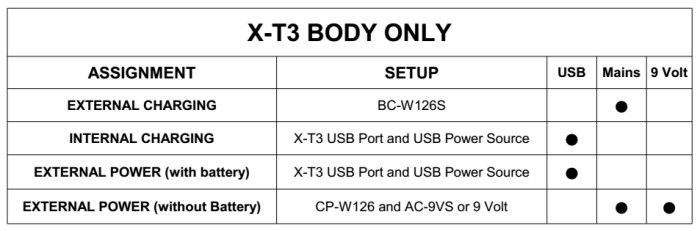
Body only power configuration options
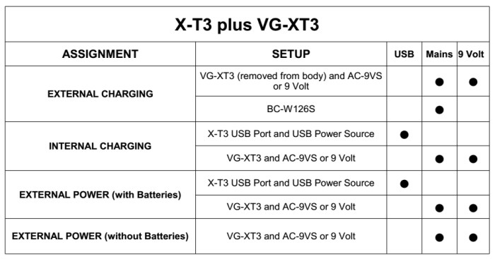
Body and grip power configuration options
B – NP-W126S & NP-W126 BATTERIES
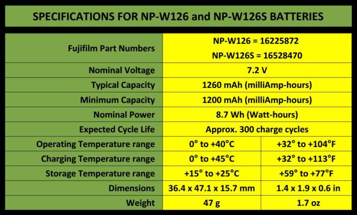
Specifications
Distinguishing between S and non-S
Performance differences
Determining the production date
C – NON-OEM BATTERIES
Genuine vs non-OEM batteries
Discharge characteristics
Identifying counterfeit batteries
D – VERTICAL GRIP
Battery discharge sequence
Battery deployment strategies
9 Volt DC input options
USB boost cable (5V step up to 9V)
E – LITHIUM-ION BATTERIES
State of health
State of charge
Calendar fade
Cycle fade
Detriments to service life
Charging
Charge rates
Charging times
Voltage limits for charge and discharge
Temperature limits
Voltage stabilisation
Measuring battery voltage
Battery contacts
Self-discharge
Storage
Determining the battery’s end of life
Li-ion fire hazard
F – POWER MANAGEMENT SETTINGS
View Mode setting
Auto Power Off setting
Power management menu
Boost mode
Performance mode differences
G – EXTERNAL CHARGERS
BC-W126S / BC-W126
Non-OEM chargers
Unexpected Interactions
Over-temperature protection
H – X-T3 USB PORT
Connection mode
Connector types
USB “Power Delivery”
Internal charging
External powering
USB power sources
Fujifilm AC-5VF power adapter
I – POWER BANKS
Advantages
Branded power banks
Port capabilities
Expected output current
Removable battery power banks
Expected efficiency
Multi-voltage power banks
Bicycle light battery boxes
Power banks recommended by Fujifilm
Capacity limits for air transport
J – DC COUPLER
Attachment
9 Volt supply options
D-Tap
Applications & examples
K – Alternative Power Supplies
Automotive power
Buck converters
How to use solar power
L – USB Power Meters
M – Disclaimer
SECTION – A
OVERVIEW
Currently (early 2019), the X-T3 camera boasts the most sophisticated and versatile power management system of any X-series camera to date. Many of its power management improvements were introduced with the X-T2 model. The significant differences between the X-T3’s power system, and the very similar power systems of the X-T2 and X-H1, are the X-T3’s adoption of the USB-C standard for USB connection, and the ability to achieve maximum performance without having to use the optional battery grip.
The electrical specifications of the X-T3, are found on the identification and compliance plates. The one belonging to the camera body, is at the back of the tilt LCD screen, and can be seen when the screen’s top is pulled outward, while the other plate is found on the top surface of the optional vertical grip. Both state that the camera is rated at 9 Volts up to a power of 18 Watts.


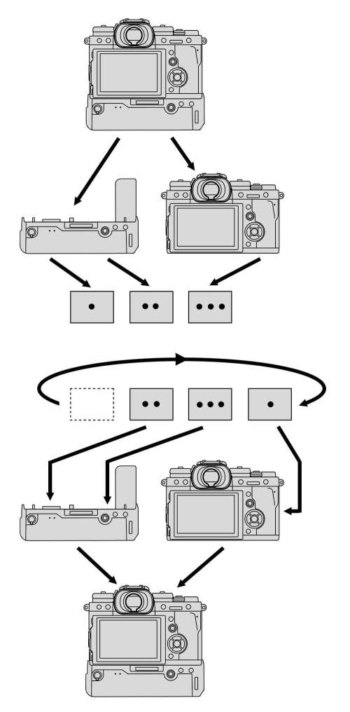
In terms of power options, use of the grip adds some, but at the same time, obstructs some others. For instance, while the grip is attached, there is no access to the camera body’s battery chamber. Because of this, there are two slightly different power configuration schemes for the X-T3, depending on whether or not the optional vertical grip is used.

When the optional VG-XT3 grip is used, it is possible to leave the grip attached quasi-permanently, since there is no need to access the body battery for external charging, (although, you still have the external charging option, if desired).


Section – B
NP-W126S & NP-W126 BATTERIES
The NP-W126S is the specified battery for the X-T3 system (X-T3 body and optional VG-XT3 grip). Because some X-T3 owners might already have NP-W126 (non-S) batteries from an earlier camera, and they would like to use those batteries in the X-T3, the distinction between the two battery types can become an issue. The newer NP-W126S battery is a higher performance version of the NP-W126 battery, and was introduced to meet the needs of the X-T2 camera. These requirements on battery capability are extended further by the X-T3’s even higher performance specification. To the question “Can NP-W126 (non-S) batteries be used in the X-T3?”, the short answer is “Yes, but the camera may not be able to perform at its highest specification potential”. For some types of photography (for instance, Landscape photography, and Product photography) a reduction in “speed” performance, may simply not be an issue.

The NP-W126 and NP-W126S batteries are identical in terms of physical dimensions and power capacity, and may be considered interchangeable for lower paced situations where top performance is not required.
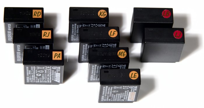
The specific internal difference between the two battery types is the lower internal resistance characteristics of the “S” version. Low resistance enables high current flow with minimal temperature rise. The readily identifiable visual indicator of battery type is the orange square on the end of regular NP-W126 batteries, and the orange circle (plus the orange insertion direction arrow) on the NP-W126S batteries.

BATTERY TYPE DISCRIMINATION BY X-T3
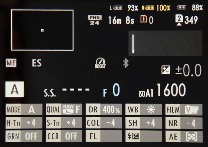
When the X-T3 is powered up, any battery that is not an NP-W126S (this includes the NP-W126, and non-OEM batteries), is identified. The X-T3 determines the type by measuring for high resistance (about 680kΩ or higher) on the [S] contact of the battery, to indicate an “S” type battery. (If you tape over the [S] contact of a non-S type battery, effectively giving it infinite resistance, the X-T3 will mistakenly recognise that battery as an NP-W126S battery). If three batteries are loaded (1 in the body, 2 in the grip), at power up, the battery symbols for the grip batteries, display briefly with the “three dots” (meaning the battery’s state of charge is being assessed). At this stage, the “S” or “non-S” battery type has already been determined, and Left and Right grip battery indicators show in either white (for “S” type) or yellow (for “non-S” type battery).

Within one second, the display shows all three battery indicators, with their appropriate charge levels, and displayed in either white or yellow. Any yellow display (meaning a “non-S” battery is detected), will be accompanied by a message recommending the use of NP-W126S batteries.
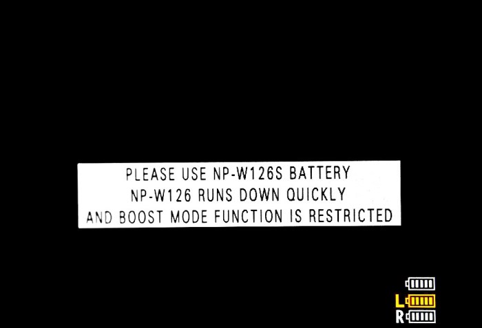
Note that the message uses the advisory “Please use …” rather than the imperative “You must use …”. This, as well as the fact that the camera continues to work, indicates that the message is to be taken as an recommendation, rather than a directive.
PERFORMANCE DIFFERENCES
The performance differences between the regular and the type-S battery, are to do with sustained high power delivery over time, rather than with stored capacity. The type-S battery was intended to meet the increased endurance requirements of the previous X-T2 camera, when operating in scenarios such as high-rate continuous stills shooting, and long duration 4K video capture. Without the higher performance battery type, sustained high power usage could produce elevated battery temperature, an increase of the battery’s internal resistance, and a drop in output voltage, leading to possible camera “lock-up” events. In a lock-up event, the camera becomes unresponsive to all controls, including the on/off switch. Typically, the batteries must be removed and re-inserted before operation can be restored. The NP-W126S battery’s lower internal resistance characteristics were designed to address such issues. At the time of introduction (for the X-T2) Fujifilm stated that the improved battery could deliver three times longer duration of continuous shooting, even under 40 ℃ environmental conditions. However, for less demanding usage scenarios, the regular NP-W126 battery should perform satisfactorily, although with limitations to the X-T3’s boost mode.
PRODUCTION DATE
The battery’s performance potential declines over time, even if not being used. Therefore, in order to assess their service viability, it is useful to be able to determine the age of the NP-W126 class batteries, via their production date. This is recorded via an impressed alpha-numeric code on the end of the battery opposite to the electrical contacts end.

NP-W126 batteries having codes beginning with T, S, R, and P, had 5 characters. For codes beginning with N, and then on all NP-W126S batteries, the code is extended to 8 characters. (Please note that very early versions of the battery, prior to having the orange orientation patch, used a different production code system to the one described here). Of the 8 characters, the first three are the date code, the middle two (usually “1A” or “2A”), are undisclosed production information, and the last three are a manufacturing plant code. Note that Day of Month codes, don’t use alphabetic upper-case “I”, to avoid confusion with numeric character “1”, one. (However, this is not an issue for Year and Month codes, which don’t use numbers at all). For similar reasons, zero, “O” and “Q”, are not used. To the camera user, it is the first two characters (indicating year and month) that are of interest.

The production date information can be decoded by using the chart below. In the above illustration, the “KGT” date code can be decoded as “2018, July, 26”. Note that the year of production code proceeds in a reverse order. As a consequence, a letter closer to the beginning of the alphabet represent more recently produced battery. Since a Li-Ion battery’s prime operating condition only lasts about two years it is worthwhile remembering the year codes representing the last two years, since these represent the batteries that are currently within their prime. Batteries beyond the two year period may still be usable for casual photography, but for critical and high power demand usage, batteries within the recent two year production period, should be preferred.

At time of release, the X-T3 should have been supplied with a battery whose production code starts with K. As we get a few months into 2019, production codes starting with J should start showing up.
SECTION -C
NON-OEM BATTERIES
Non-OEM (Original Equipment Manufacturer) batteries are also known as third-party batteries. Batteries that are “nominally” equivalent to the NP-W126, but not genuine Fujifilm batteries, (and therefore, not manufactured by Panasonic Energy Wuxi), are readily available, and at prices significantly below the price of the genuine NP-W126S batteries. Although the nominal specifications may suggest the non-OEM battery as a viable alternative to the genuine battery, there can be significant performance, behavioural, and safety differences.
GENUINE Vs NON-OEM BATTERIES
Although more costly in the short term, genuine Fujifilm batteries offer the following advantages over non-OEM batteries:
Stated capacity is reliable. The genuine Fujifilm batteries are rated at a capacity at or close to the maximum that is attainable for the technology, and their nominal capacity matches their actual capacity. Third-party batteries claiming significantly higher capacities are generally overstated.
The genuine Fujifilm batteries can fully utilise the camera and charger’s power management system. This means that all four battery contacts, [+], [T], [S], and [-], are functional. On some non-OEM batteries, the [T] and [S] contacts are either set at a fixed value, or un-connected to any appropriate circuitry. This non-functionality of the [T] (temperature control) could have safety consequences.
The genuine Fujifilm battery’s designation as a high performance “S” type, is reliable. Non-Fuji batteries can make this claim, as a pretense, by simply labelling them as an “S” type, and changing the resistance value on the [S] contact from 100kΩ to 680kΩ, without any other internal changes to the “non-S” chemistry or construction. (The camera will report this fake as an NP-W126S battery).
Production date, and so the age of the genuine battery, can be established with certainty. This can be very important for long term power management and planning. Also, if you are able to inspect a battery, before purchase, you could avoid purchasing old stock (bearing in mind that, for distribution and and logistics reasons, we could expect even the “freshest” batteries to be several months past their production date).
There could be warranty implications. If the camera was damaged as a result of a battery defect, obviously the question of whether the battery was a genuine Fujifilm battery, or a non-OEM battery, would be crucial to the outcome of any warranty claim.
Capacity against voltage profile is as expected by the system, so the battery level indicator works as it was designed to.
Extensive information regarding differences between The Fujifilm battery and non-OEM alternatives, is given in The Great Battery Brawl.
DISCHARGE CHARACTERISTICS
The relationship between, battery voltage, remaining capacity, and expected time before power is depleted, is non-linear. The discharge curve for the genuine NP-W126S battery differs from that of other batteries. Unlike the fairly simple curve of the genuine batteries, the discharge curve of the third party batteries tends to be more complex, with multiple inflections. Since the camera’s battery monitoring system is calibrated against the discharge curve of the genuine NP-W126S battery, the camera will not read the current capacity of other batteries accurately (unless the battery happens to have exactly the same discharge profile as the genuine NP-W126S battery). Unfortunately, this renders the X-T3’s ability to give detailed percent-remaining capacity information for non-Fuji batteries, not very meaningful.

TESTING THE DISCHARGE CHARACTERISTICS
Genuine NP-W126S batteries, and representative non-OEM batteries, were tested in order to establish the discharge characteristics against the battery level indicator. Each battery was fully charged using the supplied BC-W126S charger. When fully charged, the battery was removed and allowed to rest for 90 minutes, so that the open-circuit voltage could stabilise. The voltage was measured and recorded, and the battery was inserted into the X-T3. 4K video shooting was initiated. As soon as the indicator dropped by one bar (an “indicator event”), the video was terminated. The battery was removed immediately, and its open-circuit voltage measured and recorded. The duration of the video recording was used as a measure of elapsed time. The camera and battery were allowed to rest for a 10 minute cooling time, before the battery was again inserted, and video shooting re-initiated, until the next battery indicator event. This process cycle was repeated until the eventual camera shutdown, due to depleted battery.
After testing, I differentiated the results into 3 groups, which I have arbitrarily called type 1 (the genuine Fujifilm batteries), type 2, and type 3. The results for batteries within each type group, have been averaged, in order to give a very generalised view of the discharge behaviour typical of that battery type. Please note that, because the testing placed the batteries under very high stress, the results could be considered as those of a worst case scenario. You may actually get better discharge behaviour than what these results indicate.
TYPE 1 – GENUINE FUJIFILM NP-W126S BATTERIES
Because the battery level monitoring system of the X-T3 is calibrated against the genuine Fujifilm battery, the indicator symbols when using that battery, are informative, reliable, and accurate. Note that the remaining charge percentage and the remaining runtime percentage, don’t exactly match, because their relationship is non-linear.
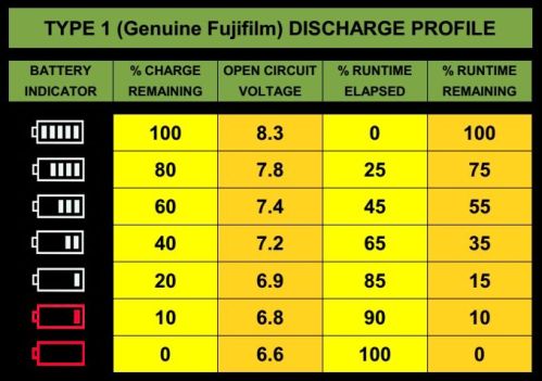
Perhaps most importantly, the indicator gives adequate warning before system shutdown due to battery depletion.
TYPE 2 – TYPICAL HIGH CAPACITY NON-OEM BATTERIES
These batteries are well regarded by some people, because they deliver similar capacity to the genuine Fujifilm batteries, but at only a fraction of the price. However, they have the least conformity to the X-T3’s calibration curve. Their actual degree of discharge is always higher than what is shown by the battery indicator, and this discrepancy increases as the battery discharge progresses. By the time the indicator displays 2 bars, the battery is almost fully discharged, and low-battery shutdown follows quickly, with little or no warning.

Notice that this type of battery may not display the one bar battery symbol, but goes straight from two bars to empty.
TYPE 3 – TYPICAL LOWER CAPACITY NON-OEM BATTERIES
These batteries are low cost, and typically have capacities in the range of 1000 – 675mAh, (which may be overstated on their label, by up to 45%). At the beginning of discharge, the actual charge remaining is slightly higher than indicated, then at about midway (3 bars) the display is fairly accurate, and finally, in the low number of bars, the actual charge remaining, is less than indicated. Due to the fact that the battery has a lower maximum capacity to begin with, full depletion is reached very quickly, when the indicator is in the low number of bars. By the time the indicator displays 1 bar, the battery is almost fully discharged. If the low-battery warning is given, shutdown might follow within a couple of seconds.
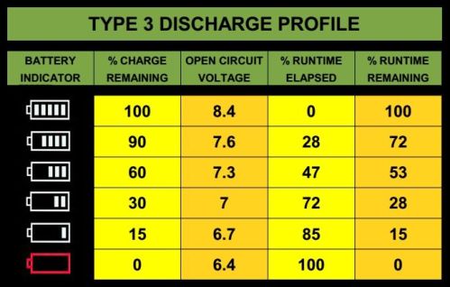
Because of their lower capacity, these batteries tend to overheat when charging, (the charging current, which has been chosen for a 1260mAh battery, is too high for the lower capacity), and so these batteries often become swollen if the charger does not implement over-temperature protection.
IDENTIFYING COUNTERFEIT BATTERIES
Simply being a non-OEM battery, does not make a battery counterfeit. To be counterfeit, there must be an attempt to deceitfully pass (via fake packaging and labeling) the battery as a genuine Fujifilm battery. Suspicions regarding the battery’s authenticity generally arise from, low purchase cost, poor performance, or the experience of the battery having a tight fit in the battery chamber. The following anomalies, (a more comprehensive list can be found in NP-W126S COUNTERFEITS: A Visual Guide to Spotting the Fakes), can help distinguish counterfeit batteries from the genuine (manufactured for Fujifilm by Panasonic) batteries:
Check the dimensions of the printed area of the suspect battery against those of a known genuine battery. When the printed information on the genuine battery was scanned for the purpose of reproduction on the counterfeit, some re-scaling may have taken place, leading to a slight difference in the bounding dimensions of the information printed on the battery.

Weigh the battery, with accurate electronic scales. Genuine batteries weigh very close to 47g / 1.7oz. Non-OEM batteries can be anywhere in a range of about 39-50g.

Check the flatness of the printed sides of the battery. Genuine Fujifilm batteries have a concavity to the sides, which can be seen by placing a straight-edge against them, and viewing against a bright background. The concavity can even be felt by rubbing over the surface with your finger. The genuine batteries will not have flat, or convex (bulging in the middle) sides.


Check the production code information on the end of the battery. Possible anomalies include: non-existent code, non-conforming code, or code that is ink-printed (rather than heat-impressed). In the following photograph, the battery with code starting KGT, is genuine, while the one with code starting MGW (printed in white ink), is a counterfeit.

A counterfeit battery may not show all of these anomalies, but it is likely to show several of them.
Section – D
VERTICAL GRIP
The Fujifilm VG-XT3 vertical grip (from this point on, simply referred to as the “grip”) is an option designed to facilitate use of the camera in “tall” or “portrait” orientation, as well as providing further power options to those given by the body alone.

The grip can be used with either two or one batteries, or even without batteries, (if you want the “tall” format ergonomics, but don’t need the weight of extra batteries). It can also be used, either attached to, or separated from the camera, as a dual battery charger. Charging takes approximately 120 minutes (when charging two batteries simultaneously) . Note that the Owner’s Manual (p. 247), states: “Use only NP-W126S batteries”.
BATTERY DISCHARGE SEQUENCE
For battery management reasons, you may sometimes want to prioritise a battery for discharge. As a general rule, the batteries are discharged starting from the left, and working towards the right. For light duty power demand, the three batteries are discharged in the following sequence: First, the left-hand grip battery, next, the right-hand grip battery, and finally, the body battery.

For sustained high power usage (continuous shooting, and high power demand video), the body battery supplements the power supplied by the currently designated-for-discharge grip battery, with the body battery being discharged at a lesser rate than the grip battery. The discharge sequence in this case is: First, the left-hand grip battery plus body battery, next, the right-hand grip battery plus body battery, and finally, the body battery.
BATTERY DEPLOYMENT STRATEGIES
You may be using a mix of batteries that differ in both type and age. The arrangement of the batteries in order of far grip battery to body battery, may have implications for your workflow. Also, certain battery arrangements could, if used for a long period of time, result in some batteries being under-utilised, and others being over-utilsed. For the sake of both efficiency and economy, it may be worthwhile putting in place an appropriate battery deployment strategy.
MIX OF “S” AND “NON-S” BATTERIES
If using a mix of non-S and type-S batteries, it is recommended to place an “S” battery in the camera body. When the batteries are assigned this way, the camera can always have access to the highest performance type battery, even if the other two batteries have become discharged.
EXPLOITATION STRATEGY
The exploitation strategy pushes your best (youngest) battery to the front of the discharge queue. This gives maximum usage value in terms of total lifetime shots against the purchase price of the battery. An advantage is that batteries are never under-utilised, and the strategy is very cost efficient. A disadvantage is that you can start with plenty of power at the beginning of a session, but the second and third batteries discharge more quickly than the first, so you may get less warning when all batteries having become depleted. It’s a good strategy if your shoot sessions are typically short.
CONTINGENCY STRATEGY (CONSERVATION STRATEGY)
The contingency strategy pushes your best (youngest) battery to the rear of the discharge queue. It considers the grip batteries as the working batteries, and the body battery as a back-up or contingency battery. Applying this strategy, when both of the grip batteries have become discharged, you should plan to replace or recharge them immediately, rather than continuing to photograph and running down the body battery. This strategy helps to ensure that you always have reserve power, so that you don’t lose power at some critical point in shooting, and also avoids having to regularly remove the grip to change a flat body battery, during the shoot. In this strategy, your “best” battery, is being kept in reserve, to ensure that you are able to cope with any unforeseen circumstances. The down side of this strategy is that the “contingency battery” may be under utilized during its typical two years of life expectation. Of course, whenever a new battery is purchased, it takes the place of the reserve battery, and the old reserve battery can be places in the grip as a working battery. This usage strategy is good for long shooting sessions, where you typically have to do battery replacements during the shoot.
ROTATION STRATEGY
This strategy distributes the usage over each of the batteries, so that none of them become overused or underused. This strategy is particularly recommended if you typically don’t remove your batteries from the camera and grip (that is, you use internal charging methods). The position of each battery in the system is rotated on a regular interval basis. An ideal interval would be a monthly cycle.
In a (say) five battery system (one in the body, two in the grip, and two spares), the two additional batteries can also be inserted into the rotation sequence, but you may have to do some record keeping, so that you can determine the correct sequence at rotation time. Be aware that, if all of the batteries were of approximately the same age, at the beginning of this strategy, they will all start to show signs of aging (decreased exposure counts) at approximately the same time (about two years on). So this strategy works better if a new battery is purchased at regular intervals (say, at the end of the first year, and then every six months), which should not be an unreasonable demand if working professionally.
9V DC INPUT
A DC power input socket (EIAJ-03) is under the rubber seal on the left-hand side of the grip.
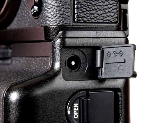
This socket is intended for the AC-9VS power adapter, that is supplied with the grip, and which can be used for both charging and supplying operational power, although not simultaneously. When the camera is turned off, the 9 Volt input will supply power for charging the grip batteries (but not the body battery). If the camera is turned on, then the 9 Volt input will supply power for camera operation.
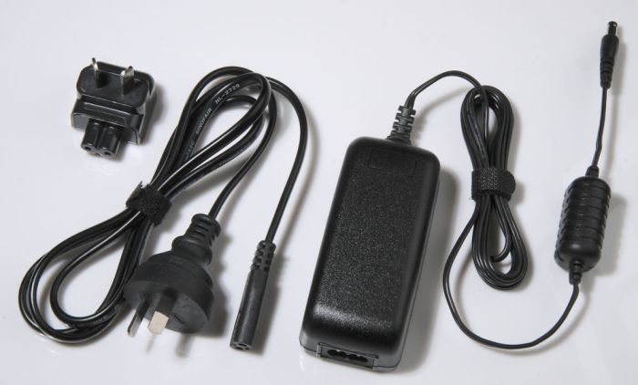
The camera can operate without batteries if powered via the 9 Volt input, although to attain the camera’s highest performance, it may be necessary for the DC input to be supplemented by some battery power, (at least one partially charged battery).
DC INPUT PLUGS
There is the possibility of supplying 9V power using power sources other than the AC-9VS. However, for operation without batteries, the voltage supplied via the DC socket, should not go below about 8.75 Volts; otherwise the display will flash the low power symbol (red battery with no bars), and the camera will auto power-off. The grip’s DC input is a standard socket complying with the relevant Japanese standards, and accepts an EIAJ-03 plug.
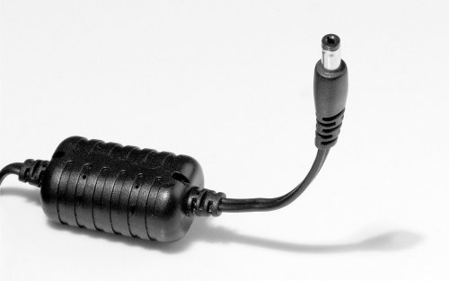
This socket is not compatible with plugs adhering to the other common standard, which is IEC 60130-10, although one of that standard’s plugs will loosely fit the socket in a way that is neither secure nor reliable. If using a 9 Volt power source other than the AC-9VS power adapter, it may be necessary to make up the appropriate cable (soldering and polarity discrimination skills required), in which case, the proper camera-end plug can be identified from the following table:

If searching online, the plug will typically be identified as a 4.8 x 1.7 mm plug. The “signature” yellow plastic tip, while common on the EIAJ-03 plug, is not unique to it, nor is it required by the standards. (In fact, Fujifilm uses a black plastic tip). However, the yellow tip can be a useful indicator of possible-candidates when searching for an appropriate plug.

USB BOOST CABLE
The USB boost cable (5V to 9V step up), is a further option for supplying power via the grip’s DC input socket. It is recommended that you only use one battery in the grip when using the boost cable (the reason is given further down). The USB boost cable can be plugged into any suitable USB power source, such as a power bank, a personal computer, or a USB wall convertor. Typically, you would need a 5.5 x 2.1mm female to 4.8 x 1.7mm male adapter or conversion cable, in order to connect the converter to the VG-XT3’s DC input socket.
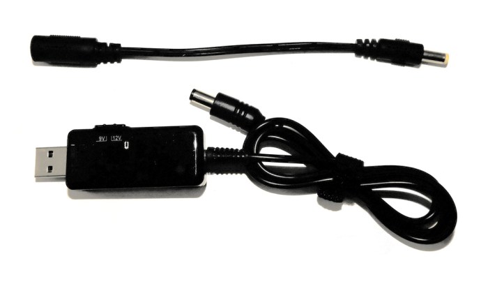
The standard USB 5 Volts is up-converted to 9 Volts, with however, a corresponding reduction in the supplied current. For example, if the power bank can supply 5 Volts at a maximum of 2 Amps (5V x 2A = 10 Watts), then the boost cable won’t be able to supply more than about 1.11 Amps of current (9V x 1.11A = 10 Watts) after the voltage conversion. The actual current will be less than this, if we take conversion losses into account, but for practical purposes, we can consider that the current is approximately halved, so 1 Amp. For comparison, the AC-9VS power adapter can supply 9 Volts at 2 Amps (18 Watts). The boost cable delivers sufficient power to supply the camera for moderate power demand stills shooting, and for grip charging of one battery.
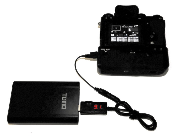
If grip battery charging of two batteries is attempted, the boost cable will demand more than the power bank’s (typical) 2 Amp total current limit, and the boost cable itself, will be pushed outside its operating limits. This will cause the boost function to fail, with inability to achieve the required 9 Volt supply. To reset the system, the boost cable has to be disconnected, and the reconnected, with the appropriate reduction in current demand. To avoid this problem, it is recommended that one of the batteries be removed from the grip, so that if the grip goes into charging mode, the limits of the boost cable are not exceeded. Unlike power delivered via the camera body’s USB socket, input through the grip’s DC socket can power the camera, even without any batteries inserted (camera or grip). Again however, keep in mind the boost cable’s limit of about 10 Watts of power, whereas for highest level of performance, more than 18 Watts (AC-9VS power adapter plus at least one battery) may be required.
Section – E
LITHIUM-ION BATTERIES
The NP-W126S and NP-W126 batteries are constructed of two series-connected metal-can type prismatic lithium-ion cells, together with a built-in power management board, all of which is sealed in a polycarbonate case.

(In what follows, “lithium-ion” will usually be abbreviated to “Li-ion”). The exact chemical composition of the NP-W126S battery is proprietary information. However, some information can be gleaned from Safety Data Sheets, lodged for the purpose of compliance with international transport regulations.

The exact transition metal component of the positive electrode is not openly specified, but the candidate metals are: Co, Mn, Ni, and Al. In what follows, specific information that was available from Fujifilm and from Panasonic Energy in Wuxi (the battery’s normal manufacturer), is supplemented by information which applies to Li-ion batteries in general.
BE CAREFUL – NOT FANATICAL
The following information is intended to assist you rather than burden you. In real life practice, it is not possible to follow all of the best advice, all of the time. We should differentiate between occasional sub-optimal battery treatment, and habitual misuse. Since the battery has a limited life regardless of how carefully it is treated, there is little point in becoming obsessive-compulsive in regard to maximising battery life.
BATTERY STATES AND PERCENTAGES
There are two commonly quoted Li-ion battery states that may both be expressed as percentages. One is the battery’s State of Health (SoH), and the other is the battery’s State of Charge (SoC).
STATE OF HEALTH
State of Health is a ratio of the battery’s present capacity for storing energy, compared to the battery’s original capacity at the time of manufacture. SoH speaks to whether the battery is, viable for continued usage, or approaching the state of being considered a dead battery. The expression of SoH as a percentage is more conceptual than practical, because the user usually doesn’t have an instrument to directly measure the SoH, and it is typically inferred from the battery’s age and performance. By definition, the battery’s capacity when new will be 100%, but this percentage will decline with time and usage. We are typically interested in the range from 100% to 80%, because when the SoH reaches a conceptual 80%, there is a noticeable fall-off in battery performance. For the photographer, this fall-off generally manifests as a reduced number of shots per charge, and around 80% is a typical point at which we might consider withdrawing the battery from primary service, and replacing it.
STATE OF CHARGE
State of charge is a ratio of the battery’s present actual deliverable energy, compared to its present potential for holding deliverable energy (which is, of course, largely dependent on the battery’s SoH). State of Charge is what is displayed by the camera’s battery level indicators. When fully charged, the SoC is 100%, but when “flat”, the SoC would be reported as 0%. Keep in mind that 0% is relative, and does not mean absolutely zero energy. Li-ion batteries cannot tolerate being at very reduced voltages, and so a certain amount of electrical potential must always be reserved, to keep the battery in a safe electro-chemical state. This reserve is handled automatically by the camera’s power management system, and generally need not be a concern of the user. But, as a consequence of this reserve, not all of the battery’s electrical energy is available for use by the camera.
To summarise, a flat battery will have a low State of Charge (say 0%) and the remedy is to re-charge it, while a dead (or dying) battery will have a low State of Health (say 80%) and the remedy is to replace it.
BATTERY LIFE EXPECTATION
As a general rule, Li-ion batteries do not suddenly “die”, but rather, they show a gradual decline in capability. Within the context of that decline, we can broadly identify a transitional phase when the battery’s performance goes from meeting expectations to failing to meet expectations. We can consider the service period up to the “failure to meet expectations” point, the life of the battery. The Li-ion battery’s life inevitably declines due to two processes known as calendar fade and cycle fade.
CALENDAR FADE
Calendar fade refers to a time related decline in capacity, which is independent of charge-discharge cycling, and which even affects batteries that are not being used. (Note that calendar fade is also accelerated by high temperatures, so it is beneficial for batteries to be kept cool). The commonly accepted rule of thumb is that, after 2 years, a Li-ion battery can only hold 80% of its original capacity. In general, at 80% capacity, although the battery is still usable, it is noticeably under-performing.
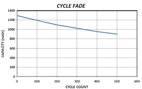
CYCLE FADE
Cycle fade refers to an in-service related decline in battery capacity due to repeated charge-discharge cycling. Fujifilm states an expectancy of 300 charge-discharge cycles for the NP-W126 class batteries (Owner’s Manual, p. 274). Again, capacity falling to 80% is the criteria for determining expected cycle numbers.
BALANCED USAGE
If we try to balance these fade processes by aiming for the calendar fade endpoint and the cycle fade endpoint to coincide, (300 cycles distributed over a period of 24 months), we are looking at roughly 3 charge-discharge cycles per week, for a single battery. We can consider this as a hypothetical standard-usage-density for the purpose of determining whether the battery is being over or under utilised.
NEW BATTERIES
The Owner’s Manual (p. 28) states: “The battery is not charged at shipment.” New batteries are delivered with approximately 30% SoC. This is partly to extend service life by keeping the battery in a preferred storage state until the user has taken delivery of the battery, and partly due to transport regulations, (specifically, transportation by cargo aircraft under UN3480, Class 9 Dangerous Goods category, with state of charge not exceeding 30%), since Li-ion batteries are safer (less likely to enter a thermal-runaway condition if subjected to elevated temperatures) at a lower SoC. The new battery may have to be charge and discharge cycled about three times before it gives normal charge and discharge behaviour. This is because Coulombic efficiency (the ratio of the total charge extracted from the battery to the total charge put into the battery over a full cycle), improves with cycling. Previous to the battery being cycled, its Coulombic efficiency may have been between high-80’s to mid-90’s percent. After a small number of cycles, it can approach 99% or higher. Some batteries have already been cycled by the manufacturer, before delivery.
DETRIMENTS TO SERVICE LIFE
The following situations or conditions should be avoided to ensure that the Li-ion battery is not un-necessarily stressed.
• Avoid high temperatures (should not be subjected to > +45°C or +113°F)
• Avoid ultra-fast charging (Rate of charge greater than 1C)
• Absolutely avoid charging at temperatures below 0°C.
CHARGING
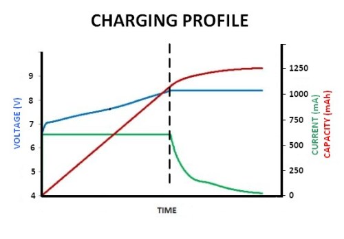
Li-ion batteries are charged according to the constant voltage (CV) / constant current (CC) method. The charge process has two main phases. In the first phase, the current is constant, at a value determined by the selected C-rate, the voltage steadily climbs, and the increase in charge, over time, is linear and rapid. In the second phase (saturation phase), when the maximum charge voltage (8.4 Volts) has been reached, the voltage becomes constant, the current drops rapidly, and the increase in charge, over time, becomes non-linear, and slower. If charging is being monitored, the rapid drop in current is a good indicator of the position in the charge process. Charging terminates when the current drops below a threshold (0.1C is typical).
CHARGE RATES
Battery charging times are mainly dependent on ambient temperature and charging rate. Charging rate, or C-rate, is the expression of charging current normalized against battery capacity. For example, when charging with a rate of 1C, a 1200mAh capacity battery would be charged at a current of 1200mA, and would be fully charged in 1 hour (theoretically). Note however, that a rate of 1C is considered to be higher than optimal, and the recommended fast charge rate is 0.7C. Because very high rates of charging are detrimental to the long-term condition of the battery, high-rate charging is usually terminated earlier in order to avoid detrimental effects. As a consequence, the available capacity changes per different C-rates, with the higher C-rates typically producing slightly less available capacity.
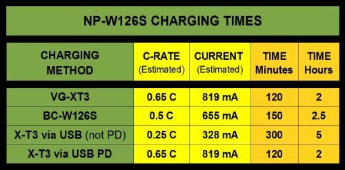
CHARGING TIMES
The X-T3’s different charging methods use different charge rates, and as a result, have different charging times. Of the available charging methods, charging via the grip uses the highest rate, and can charge two batteries simultaneously. Charging via the camera body’s USB port (if not using USB PD or “Power Delivery”) has the lowest charge rate and, although the slowest method, is probably the best for the battery, both in terms of available capacity, and long-term battery health.
If using an external power monitor, be careful not to confuse input current with charging current. You can avoid this problem by working in Watts (current x voltage). For a USB input, the voltage will be 5 Volts (even for USB PD). For charging, the voltage will be 8.4 Volts. USB PD is explained more thoroughly in Section H, about the X-T3 USB Port.
PARTIAL CYCLING
Li-ion batteries do not have any significant memory effect, so there is no absolute requirement for Li-ion batteries to be fully-cycled on a regular basis. They can be partially cycled, but be aware that the various part-cycle patterns can differ in their beneficial or detrimental contribution to long term battery health. Ironically, (and different from many other battery types), the “fully charged” state is more stressful to the Li-ion battery than lower states of charge, and leaves the battery more susceptible to electrolyte oxidation, which is cumulatively detrimental to its life, each time the fully-charged state occurs. Therefore, full cycling (fully charge, then fully discharge), is preferable to “top-up-to-full” partial cycling, because, in the long run, it results in fewer instances of being “fully charged”.
If you know that a shoot will only require a small number of shots, (perhaps a couple of dozen), then there is no problem with giving a discharged battery a shorter charge , say 40 to 60% of full capacity. Routinely charging the battery to slightly less than full capacity (90% would be ideal), has a beneficial effect on battery longevity. However, the reduced number of shots per charge is not acceptable to most photographers.
VOLTAGE LIMITS FOR CHARGE AND DISCHARGE
Automatic chargers should implement protections against over-charging, and the camera should implement protections against over-discharging. The battery also has its own internal protective circuit to guard against over-discharging. Limits are according to the following significant voltages:

Although there are automated systems in place to guard against over-charging and over-discharging, poor usage practices can effectively put the battery slightly into the over-charged / over-discharged state. Slight over-charging can result from repeatedly putting an already fully charged battery back on the charger. Slight over-discharging can result from repeatedly turning on again, a camera that has displayed the battery empty sign and automatically switched off.
TEMPERATURE LIMITS
Li-ion batteries are noted for their wide range of operational temperature compared to many other battery types, however, they are very sensitive to temperature beyond that operating range.

As temperatures become elevated, initially the battery sustains internal damage which impacts its long-term performance, then at very high temperatures, the battery starts to sustain damage which can pose serious safety risks. Li-ion batteries contain flammable electrolyte that may vent, and spontaneously ignite when subjected to temperatures above +150℃ or +300°F. When ignited, Li-ion batteries can burn rapidly with flare-like burning effect, and may ignite other batteries in close proximity.
VOLTAGE STABILISATION
After a full charge, the open-circuit voltage of the battery (as checked with a multi-meter) will decrease rapidly in the first 10 minutes and then gradually over the next few hours before stabilising. If you intend using voltage as a guide to battery condition, rest the battery for 90 minutes after charging, before measuring the voltage. The stabilised voltage is a better indicator of SoC than the voltage measured immediately after charge termination, and you are likely to get better power metering by the camera if you begin using the batteries after they have stabilised. This supports the practice where, if you have to charge batteries for a shoot, it is preferable to charge them the night before the shoot, rather than immediately before the shoot.
MEASURING BATTERY VOLTAGE
If you have the requisite background knowledge, and are comfortable with using a digital multimeter (DMM), you can use the battery’s open-circuit voltage as a surrogate for battery state and condition. Since these measurements do not assess the battery under load, they cannot account for load related voltage drop, however they are useful in giving further information for battery assessment and comparison. It should be noted that instantaneous voltages during charging, and instantaneous voltages during discharging display hysteresis. That is, they follow different curves, showing discrepancies in the region of up to half a Volt, with lower voltages presenting for the discharge curve. Therefore, voltages during charging and during discharge are not suitable for comparison.

When doing these static measurements on the battery, the only contacts of interest will be the positive and negative contacts. For measuring the open-circuit voltage, set the DMM to DC voltage measurement, and make contact with the probes for just enough time to get a stable reading. Measurements should be made to the nearest tenth of a Volt.
NP-W126 BATTERY CONTACTS
The NP-W126 class batteries have four gold-plated electrical contacts, marked with [-], [S], [T], and [+] symbols.

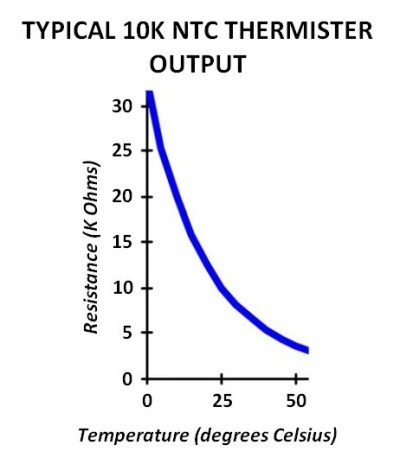
The [T] contact pertains to temperature management, and should connect to an NTC (negative temperature coefficient) thermistor, with a nominal resistance of 10kΩ at 25°C (±5% or better, typical). The resistance of the thermistor drops (with a non-linear output) as temperature increases. [To give an example: The NP-W126S battery was temperature stabilised at the room temperature of 15°. The resistance reading from the thermistor was 13.5 kΩ. Then, the battery was placed under the armpit for 5 minutes, to warm it. After warming it, the thermistor reading was found to have dropped to 9.5 kΩ]. The thermistor allows temperature monitoring while charging. Li-Ion batteries typically increase 5°C (9°F) in temperature during charging, as a normal consequence of the chemical process involved. But, the battery should not be allowed to increase more than 10°C (18°F) during charging, nor is charging allowed at more than 45°C, or less than zero°C, in order to avoid shortened battery life, lithium plating at the anode at sub-zero temperatures, and over temperature hazards such as battery swelling, venting, and thermal runaway.
When attempting to charge the NP-W126 class batteries, in the X-T3 camera, or either of the two Fujifilm chargers, if a resistance indicating a temperature within the safe range is not seen at the [T] contact, then charging is not initiated. (This safety function is also implemented on the Nitecore FX1 USB charger). On non-OEM batteries, the [T] contact is usually just connected to a fixed 10kΩ resister (meaning that it always signals the temperature as OK, even if it is outside the acceptable limits). This allows the batteries to be charged, without adhering to the safe charging temperature protocols.
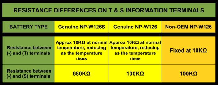
The purpose of the [S] (probably standing for “Status” or “System”) contact is not openly documented. The [S] contact most likely accesses a simple system indicator, that gives battery information by whether or not a measured resistance exceeds certain thresholds. Such a method is expandable over time, so that if a new further improved battery became available, another higher resistance threshold can be added to the system, to indicate that battery. Note that the X-T3 camera differentiates between “S” and “non-S” type batteries, by interrogating the resistance on this [S] contact.
SELF-DISCHARGE
Typical self-discharge rates for Li-ion batteries (at a temperature of about 20°C) are 5% in the first 24 hours after charging, and then 5% per month (this monthly five percent is made up of approximately 2% intrinsic loss, and 3% due to drain by the battery protection circuit).
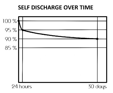
As a rule of thumb, the self-discharge rate doubles with every 10°C increase in temperature.
PLANNED DISCHARGE
Sometimes, we may wish to intentionally either partly or fully discharge a battery, for example, for testing purposes, or in preparation for storage. The X-T3 camera does not provide a specific discharge function (Some cameras do, for example Samsung NX1). For the X-T3, the best way to discharge the battery is through normal usage, just by taking photographs or video. There may be situations where your purpose is only to take the battery’s SoC just out of the fully-charged zone (one of the more stressful states of battery condition). For example, you may have charged the battery in anticipation that it would be used, but it turns out that you won’t be needing it, and the battery faces an extended period of non-use.
In such a case, you can slightly discharge it by the following method. Put the battery in the currently assigned discharge position (the left-most position if using the battery grip), attach the supplied EF-X8 shoe mount flash unit to the X-T3, and take a few shots using the flash. The EF-X8 has to be used, since it draws its charge power from the X-T3 batteries. (Incidentally, occasional use of the EF-X8 flash, is good for the X-T3’s flash capacitor, and helps to keep it “formed”). Another method is to take some video at a high frame rate and resolution (it doesn’t need to be 4K video). It is not recommended that you discharge by taking long duration continuous-shooting bursts using the mechanical shutter, because this will cause unnecessary wear-and-tear on the shutter, which although rated at several hundred-thousand actuations, never-the-less has a limited lifetime.
STORAGE
Conditions of storage (an extended period of non-use) have an impact on the life expectancy of the battery. The most significant factors are, the battery’s State of Charge (SoC), and the ambient storage temperature. A Li-ion battery’s state of least stress is about 40% SoC at 15°C (59°F). This is represented by 2 bars on the X-T3’s battery level indicator.
DOWN TIME
If the battery will not be used for several days, or even a week, this period can be considered normal down-time, rather than a storage period. The battery can be left in its present state of charge, although leaving it in a fully charged state is not ideal, and should not be a target for a regular down-time state.
SHORT-PERIOD STORAGE
If it is estimated that the battery will be in a storage condition for a few weeks, “half-charged” is an appropriate level. However, it is also OK to leave the SoC at an effectively “flat” level. A battery which has just gone flat (according to the camera), is still well above any damaging over-discharge voltage. An ambient temperature of +15°C is optimal, but since the period of non-use will be short, a storage temperature in the range -10 to +40°C is OK.
LONG-PERIOD STORAGE
If it is estimated that the battery will be in storage for a period of months (this could happen if you were going to be away from home for an extended period of time, and you are taking a different camera with you), it is recommended to have the SoC of the stored battery at 40 – 50%, indicated by between 2 or 3 bars on the X-T3’s battery level indicator. This places the battery in a low stress condition, but also allows for inevitable self-discharge (about 5% per month) to take place, without the battery over-discharging. The battery should not be stored in the camera, due to further discharge by quiescent current. (Quiescent current flows due to the camera awaiting any wake-up signal from the power switch, and also from powering the clock-calendar). An alternative method of assessing a battery’s readiness for storage is by measuring its voltage. A battery in good condition will have a stabilised open circuit voltage of about 7.6 Volts when its SoC is about 40%.
If initially stored at 40% SoC, after about 8 months the battery may be close to flat, so it would be good if the stored battery could be given a part charge (back to 40 – 50%), say about every 3 – 6 months. At any rate, a battery should be charged at least once per year. A storage temperature of +15°C is optimal, but up to +25°C is acceptable, however it is not recommended to store the battery outside the range of 0 to +35°C.
KEEPING CONTACTS CLEAN
Keeping the battery’s gold-plated contacts clean can help attain optimal charging and usage conditions. Contacts can become dirty from inadvertently touching them, or simply by the deposition of air-borne grime (particularly in cities, where the presence of diesel fuel particulates and other pollutants can be significant). A cotton-tip is useful to buff the contact surface. No liquid or solvent should be used.
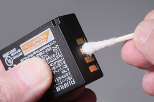
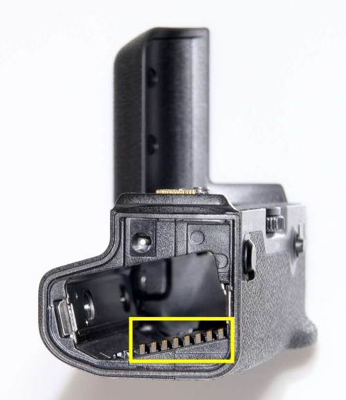
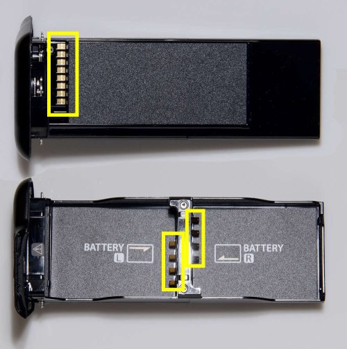
Keep in mind that there are numerous contacts in the power supply chain, and they all need to be kept clean. However, be very careful not to catch and bend any spring contacts.

IDENTIFYING INDIVIDUAL BATTERIES
For the purpose of battery management, it is useful to be able to identify each individual battery, by labeling them. No stickers should be attached to the sides of the battery, due to the possibility of jamming in the battery chamber. A convenient place to write (using a fine tipped permanent marker), a number, letter or symbol for individual battery identification, is the orange orientation patch (square or circle) at the end of the battery. The manufacturing year and month code letters are convenient identifiers. Unless several batteries were purchased at the same time, and they came from the same production batch, the production codes are likely to be unique, for each of your batteries.
If you have to use non-OEM batteries, you can put a small sticker in the same position as the NP-W126 class battery’s orange orientation patch. Since you probably won’t know the production date of the battery, you can arbitrarily assign it a production date three months prior to the purchase date, (this allows for some shelf time with the vendor, before purchase). You can give it year and month code letters, according to the Fuji system, so that any management records follow a consistent method.
DETERMINING THE BATTERY’S END OF LIFE
A battery is effectively dead when the photographer rejects it due to poor performance. A battery that has been used properly does not suddenly cease working, but it does eventually reach a point where its performance no longer meets the requirements of the photographer. This point will differ slightly from person to person, depending on their usage style and workload demands. Specific signs of a dead or dying battery are:
• Uncharacteristically long or short charging times
• Very rapid self-discharge
• Noticeably decreased number of shots per charge.
SoH LOOK-UP-TABLE
Based on the typical signs of a dead or dying battery, the photographer will develop a feeling about how a particular battery is doing. However, this type of assessment can be very subjective. A more objective criteria of the battery life condition (State of Health – SoH) can be obtained from the stabilised (90 minutes after-charge) open-circuit voltage. It is not possible to give a universally applicable look-up-table (LUT), because battery usage routines (as well as user expectations), and local environmental conditions, will cause variation in the typical voltages reflecting the various states. However, it is possible to compile your own personal LUT over time, if you are prepared to take measurements and keep records. A SoH look-up-table, may be similar to this:
 This method is useful if you want to keep records, for comparison, of battery condition at regular intervals, because it yields a number.
BATTERY AUDIT FORM
A convenient way to keep records of battery condition is a battery audit form. This could be either on paper, or a computer spreadsheet. On the form, you record the open circuit voltage (90 minutes after charging), of each battery.
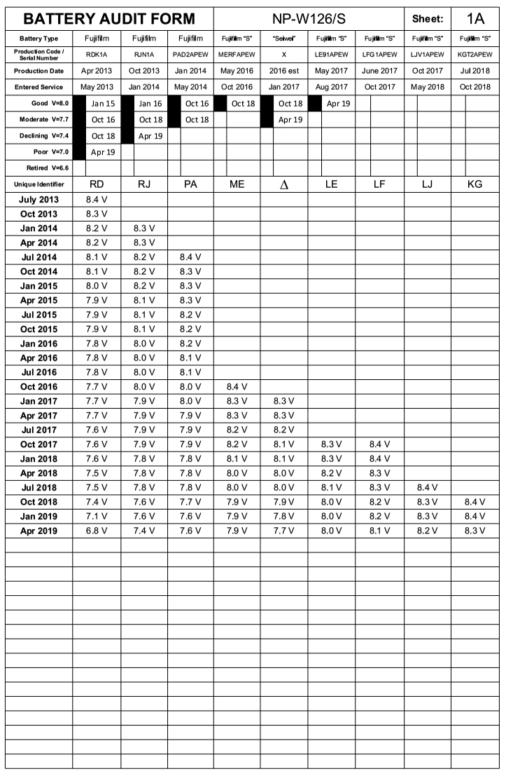
This is done at regular intervals; three monthly (that is, four times a year), would be an appropriate interval. Just do it sometime during the designated month – it is not necessary to do it on a specific date. The form also allows you to record the reaching of significant voltage thresholds (based on the SoH look-up table).

A PDF file of the audit form can be downloaded here: Battery-Audit-Form.PDF
PRIMARY AND SECONDARY BATTERY SERVICE
Batteries that are beyond the two year or 300 cycle stage, although no longer in their prime condition, are still useful. While the best batteries are kept for operating the camera at its top performance (primary service), the aged batteries can be assigned to secondary service tasks. Such tasks include:
• Back-up batteries
• Batteries for short or low shot count sessions
• Hold-over batteries
Hold-over batteries are useful if you recharge all batteries directly after a shoot, in readiness for whenever the next shoot will occur. If the camera is left unused for days or weeks, the first battery in the discharge sequence will lose some of its charge (due to quiescent current, waiting for power-up signal, and maintaining the clock and calendar system). That same battery would maintain more of its charge over the same period of time, if not left in the camera. To avoid this “stand-by” discharge of the battery, when you are not using the camera, you can replace the first battery with an old battery, and just swap in the newer (still well charged) battery, before the shoot.
JUST IN CASE vs JUST IN TIME
“Just in case” and “Just in Time” (JIT), indicate two different approaches to what “triggers” you to recharge your camera batteries. Should you recharge them immediately after a shoot (so that they are ready to go), or should you leave them in their post-shoot state, and recharge them just prior to the next shoot? There is no universally correct answer, because it will depend on your usage style, workload demands, and also your ability to know in advance when the next shoot will be, or even to exercise your own discretion about when shoots will occur. Keep in mind that, when a Li-ion battery has gone flat during a shoot, there is no problem leaving it in that state for some days, or even weeks (just let it have some “down time”). A Li-ion battery is very different from a lead-acid car battery, which should not be left in a discharged state. However, as to the long term affects on battery life, it is probably more beneficial to, where possible, let the immanence of usage be the trigger for recharging (just in time), rather than letting the conclusion of usage be the trigger for recharging (just in case). This is because, with charging directly after the shoot, if you wait some time before the next shoot, the battery has been left longer in a fully charged state (not optimal for battery longevity), and you are likely to give the batteries a top-up charge before the next shoot anyway. This results in more charging than is absolutely necessary. Furthermore, Li-ion battery service life benefits from sustained (many hours to days) relaxation periods following discharge and before re-charging.
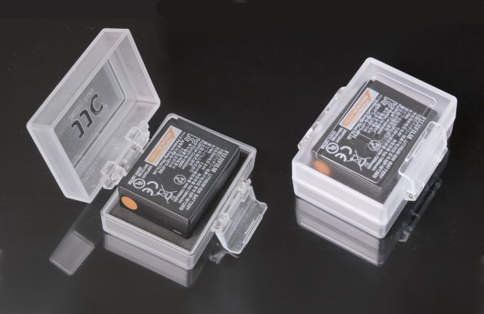
BATTERY CASES
Battery cases are useful in order to protect against accidental shorting of the power terminals, and give a convenient means of distinguishing between charged and discharged batteries. Also, in accordance with IATA regulations, pouches or cases are necessary if spare batteries are to be carried (in carry-on baggage only) while traveling by air-transport. New NP-W126S batteries, when purchased as an accessory, are supplied with a plastic soft pouch.

However, if you would like a hard case, those designed to fit the Nikon EN-EL9 battery, are suitable (although slightly longer than necessary). You can cut some dense (non-conductive) foam plastic to fill the extra length, and stop the battery from rattling in the case. The internal dimensions of any suitable battery case, need to be at least 47.5 x 36.5 x 16 mm.

For working in harsh environments, sealed weather-proof cases are also available.
IDENTIFYING CHARGED / DISCHARGED BATTERIES
If spare batteries are kept in a pouch, or battery boxes, a simple method of distinguishing between charged and discharged batteries, is by inserting the batteries with the contacts facing either inwards or outwards, to signify charged or discharged. Alternately, if you use many batteries, you can have two battery pouches, one for charged batteries, and the other for discharged batteries.


LI-ION FIRE HAZARD
If a Li-ion battery develops an internal short-circuit, this can be the prelude to a thermal-runaway event that eventually causes the battery to rupture or vent, and spontaneously ignite. Other triggers for catastrophic battery events include: faulty charging, accidental short circuit by contact with metal objects, use of the camera or batteries outside of allowable limits, and heavy trauma to the camera. The fuel for the ignition is the electrolyte content of the battery, rather than lithium metal. Although lithium metal reacts violently with water, lithium-ion batteries, contain very little metallic lithium. As a consequence of the sparse metallic lithium content, water is a suitable and recommended extinguisher for burning Li-ion batteries, such as the NP-W126 types. There are two goals in extinguishing a Li-ion battery fire: First, to extinguish the initial fire, and second, to cool the immediate surroundings to avoid the ignition of other Li-ion cells. It should be remembered that a single NP-W126 type battery contains two Li-ion cells, so the X-T3 camera and grip (3 batteries in total) holds 6 cells, and each one will ignite in series (with a delay of between several seconds up to several minutes between each ignition), if the local temperature is not significantly lowered. Water is the best medium for lowering the temperature. However, covering the extinguished batteries, even with ice cubes, is not recommended, because it tends to form an air pocket which traps and retains the heat, leading to re-ignition.
Section – F
POWER MANAGEMENT SETTINGS
Mirrorless cameras, such as the X-T3, are inherently more voracious for power than DSLR’s. The specific difference in power requirements is the mirrorless camera’s use of an electronic viewfinder (EVF), or continuous use of the LCD monitor. The key to getting power consumption that approaches that of the DSLR, is to configure the EVF and LCD monitoring system, so that they are not turned on more than they need to be.
VIEW MODE SETTING
The most power efficient View mode option is “EVF ONLY + Eye Sensor”, because it results in the viewing system being on for the least possible time. “Putting your eye to the viewfinder turns the viewfinder on; taking it away turns the viewfinder off. The LCD monitor remains off”. The view modes can be cycled through by pressing the view mode button on the right side of the EVF housing.

AUTO POWER OFF SETTING
Try to set the Auto Power Off function to the shortest interval that you can comfortably work with. Wake-up from automatic power-off is achieved in less than one second by simply half-pressing the shutter button.
POWER MANAGEMENT MENU
Auto Power Off and Performance settings are accessed through the Power Management sub menu of the Camera’s Set-Up menu. For convenience, the Performance (Boost) setting can be assigned to one of the function buttons. However, this is not necessary when the optional grip is used.
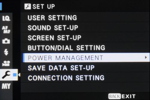
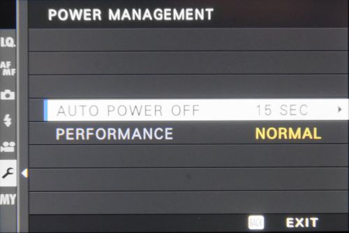
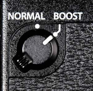
When the grip is attached, the “Performance” menu option, is greyed out, and unavailable, (to avoid selection conflicts) because the grip has its own dedicated performance (normal or boost) switch.
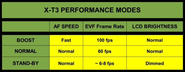
BOOST MODE
Unlike the X-T2 and X-H1 cameras, the X-T3 is able to realise top performance even without the optional battery grip. The high performance mode is called boost mode. When the highest performance is not needed, the camera can be set to Normal mode. In Normal mode, to conserve battery power, after ten seconds of inactivity (no button, dial, or touchscreen activation), the displays revert to a stand-by mode (low brightness, and very slow frame refresh rate). The display leaves this stand-by mode if there is a control activation event, or if the power mode is switched to Boost. There are no menu options for modifying this behaviour. However, if you are not using functions that that take a high power drain (continuous auto-focus, continuous high-rate stills shooting, and high resolution video), then leaving the camera in Boost mode should not produce any significant run time deficit.
According to the advisory message displayed when non-S type batteries are loaded, “Boost mode function is restricted”. The exact restrictions, for this situation, are still being compiled. (I will update this guide, as further information becomes available).
Section – G
EXTERNAL CHARGERS
BC-W126S / BC-W126
The release of the X-T3 was accompanied by the introduction of a new battery charger. The newer BC-W126S is the charger generally supplied with the X-T3 camera, although, the Owner’s Manual (page xix) states: “A BC-W126 battery charger may be supplied in place of the BC-W126S in some countries or regions”. The two chargers are interchangeable, and either charger can be used for either battery (NP-W126 or NP-W126S).
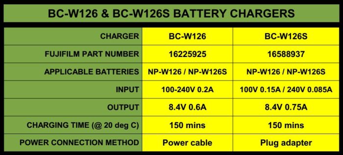
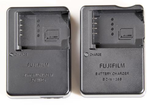

The two chargers differ in two main points: The method of connecting to the mains supply, and the slightly increased maximum output current by the BC-W126S. (Does the newer charger differentiate between the older NP-W126 and the newer NP-W126S batteries, when charging them? I don’t know yet, but keep in mind that the two battery types have a different resistance level on their [S] contacts, so the charger may differentiate, and charge them slightly differently. But, that’s pure speculation. I will try and test this when I make a break-out box for the charger.)
NON-OEM CHARGERS
Some non-OEM chargers can deliver functionality and flexibility not available from the standard supplied charger. Beyond cost, you should consider how the charger fits in with your workflow and approach to photography. It is also important to remember that the quality of the charger can have a significant effect on short-term and long-term battery performance and service.

UNEXPECTED INTERACTIONS
Power banks utilise a voltage converter circuit to change the battery voltage to the required USB supply voltage. Power is lost due to the conversion process, so it is typical for power banks to turn off the conversion circuit, if the power bank senses that the connected device no longer requires power. (The power bank will assume this if current draw falls below a certain threshold). At the same time, some chargers (typically, “smart” chargers), may momentarily suspend charging at regular intervals, in order to take measurements of the battery’s state of charge. If the power bank’s checking of the current flow, and the charger’s checking of the charge state happen to coincide, the power bank may momentarily shut down. After the smart charger’s state of charge check, the power bank will sense the charger’s need for power, and power up again. This gives the unexpected behaviour that the pair of devices “power off” momentarily, and then resume operation. The momentary power interruption does not affect the charging of the batteries, but it does have the effect of causing the charger’s count of accumulated milli-Amp hours (mAh) to reset back to zero, each time a power interruption occurs. I have experienced such an effect when powering the Nitecore FX1 with some power banks (including Tomo). However, if you place a USB power monitor in-line between the power bank and the charger, it can sometimes act as a buffer, so that power interruptions tend not to occur, and the effect of the mAh count resetting is avoided.

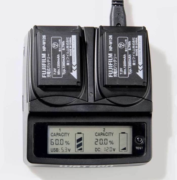
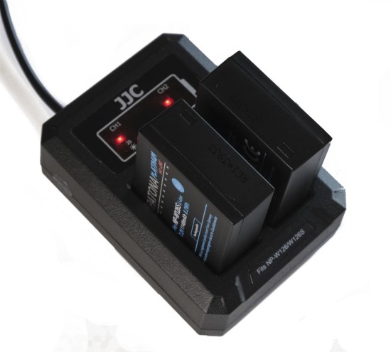
OVER-TERMERATURE PROTECTION
One very important factor, when considering non-OEM chargers, should be, whether the charger implements any kind of temperature monitoring, while charging. This will mean, either the ability to monitor the NP-W126S or NP-W126 battery’s thermistor (on the battery’s [T] contact), or the charger having its own built-in temperature sensor. Over-heating the batteries while charging will produce cumulative damage to the batteries (noticeable as as a decline in the battery’s performance, or as swelling, or venting of electrolyte reduction gases). Two third-party battery chargers that are known to implement battery temperature management are, the JJC DCH-NPW126 dual slot USB charger, and the Watson Duo Charger, dual slot AC charger (both chargers utilising in-charger battery temperature sensors). The Nitecore FX1 dual slot USB charger (utilising a third battery contact to monitor the battery’s thermistor output), reports the internal temperature of the genuine Fujifilm batteries (not of non-OEM batteries, however), and it should be noted that it does not terminate charging if the temperature exceeds the allowable temperature range – the user must do that.
Note that if the battery is non-OEM, and does not implement a working thermistor, then a charger’s thermistor monitoring function will be ineffective, since there is no genuine temperature information to monitor (only the battery’s fixed 10kΩ output by the [T] contact, which flags a “within acceptable temperature range” status, required by the Fuji charger before it will initiate charging).
Section – H
X-T3 USB PORT
The X-T3 camera has a USB type-C (USB 3.1 Gen 1) connection port. As well as its data transfer function, the port can also be used to input 5 Volt power for charging the battery in the camera body, or to assist powering the camera’s operation.

MODE SELECTION
Because the X-T3 has tethered shooting functionality, connection of a USB cable can trigger unexpected camera behaviour, if the Set Up Menu’s “PC Connection Mode” setting is not appropriate. How the 5 Volt supply is utilised depends on camera mode (off, shooting, or playback), as well as the PC Connection Mode menu settings. If not tethering to a computer, a relatively trouble-free setting is “USB Card Reader” mode.


CONNECTOR TYPES
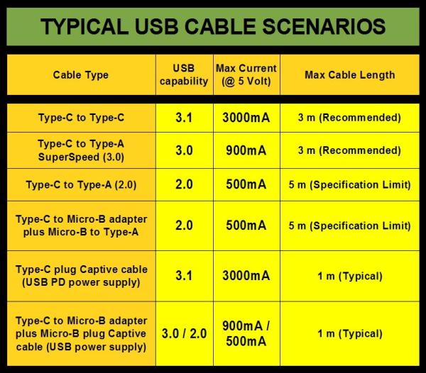
The USB socket accepts a USB type-C plug. However, depending on the type of device used for charging, the cable could be either a USB type-C to type-C, or a USB type-A to type-C cable.


According to USB standards, the X-T3 is considered a high power device, since it requires at least 500mA from the USB supply.

Since all of the USB standards from 2.0 onward can deliver at least 500mA (composed of an allowed maximum of 5 x 100mA load units, as defined under the USB standard), most USB compliant outputs meet the X-T3’s charge requirements. It is best to use the highest current-capability port for powering or charging. If the device manufacturer has implemented port colours, they can be a convenient method of differentiating between the power capabilities of different type-A port options, on a desktop or notebook PC. Port colours are not mandatory, however, members of the USB Implementors Forum (USB-IF), tend to assign the colours consistently. Of course, if the power output port is a type-C port, you can assume that it is USB 3.1 standard.

If you have previously been working with USB 2.0 and 3.0 charging methods, and using type-A and micro-B connectors, the X-T3’s adoption of the type-C connector does not mean that your previous charging system needs to be replaced. As long as the system terminates in a type-C connector, for connection to the X-T3, you can continue as before.

It should only be necessary to acquire a new type-A to type-C cable, or even a micro-B to type-C adapter, if a charger has a fixed cable (“hard-wired captured cable”). These plug adapters can also be used on legacy cables (earlier generations than type-C). The converse scenario might occur if you have acquired a USB power supply with fixed type-C cable, and you want to charge a power bank, or use a USB battery charger, that only has a Micro-B input port. In this case, a type-C to Micro-B adapter with the genders reversed can be used to make the connection for charging.

Please be very careful. These adapters are very small, and therefore dangerous to leave within reach of infants and small children, who might put them in their mouth, with the risk of choking.

It should be noted that the USB type-C standard implements two Control Channel pins (CC1 and CC2) on the type-C connector, and these are used to establish and manage the Source-to-Sink connection. Since legacy cables and connectors do not implement these Control Channel lines, attaching type-C adapters to a legacy cable will not convert it to a “full featured” type-C compliant cable. However, it can still produce a functional USB power transfer cable.
USB “POWER DELIVERY”
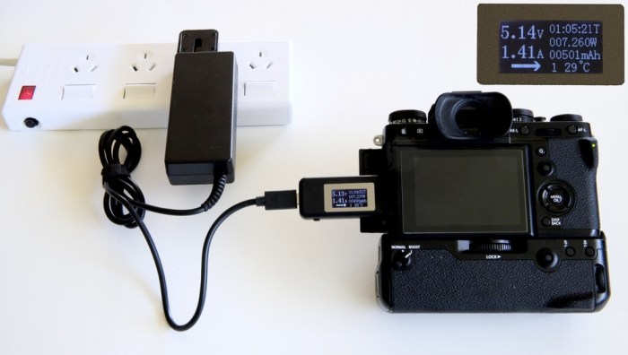
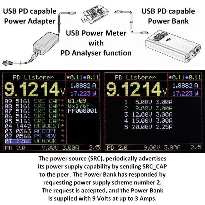
What happens if the X-T3 is connected to the USB PD (Power Delivery) port of a computer, power bank, or to a USB PD power supply? We know from experience that if the X-T3 is connected to a USB PD power supply with a hard-wired captured cable (so that there is no doubt that the cable is PD aware, compliant, and capable of conducting high currents), the X-T3 will draw 5 Volts at up to 1500mA for charging, or operation in video mode. In stills photography operation, the current draw is considerably less. In contrast to this, when the same USB PD power supply, is used to charge a 20000mAh PD power bank, the power bank draws 9 Volts at 2000mA.
Because the X-T3 has a Type-C port (which people often associate with PD), and because Fujifilm has recommended external USB power via the Anker PowerCore powerbanks (which support PD), there might seem to be the implication that the X-T3 supports elevated power levels via the PD functionality. However, as far as I am able to establish, the X-T3 does not require or negotiate elevated PD power levels (that is, power above the PD default), although it is compatible with USB systems that do support PD. So, if a charger, power bank, or PC conforms with the general USB specifications, it can be used to supply USB power to the X-T3, whether the device supplying the power supports PD or not. The following (printed in red) is simply to explain how PD works, and why we can say that the X-T3 does not negotiate elevated power levels.
USB Power Delivery (PD) is designed to co-exist with standard USB Battery Charging implementations. The USB Power Delivery protocol requires the following steps: Connection, Default Operation, Discovery, Negotiation, and Contract Operation. When a USB host and device are first connected, the initial operating conditions are the USB Default Operation, which assumes a DFP (Downstream Facing Port) supplying vSafe5V (a voltage level of 5 Volts, which is safe for all USB devices) over the VBUS line, and a UFP (Upstream Facing Port) consuming power from the VBUS line. In the case of USB PD compliant equipment, once these default conditions are set, a Discovery process can begin, if the connecting cable meets requirements. Discovery comprises the exchange of structured VDMs (Vendor Defined Messages) resulting in identification of the Port Partner, its supported SVIDs (Standard / Vendor IDs) and Modes. After the Discovery process, power Negotiation begins. The Source (power supplier) advertises its capabilities, and the Sink (device which will consume the power) requests one of the advertised capabilities. Then, the Source acknowledges the request and alters its output to satisfy the request. The result of this process is a Contract for power delivery/consumption between the two port partners. The contract specifies both power level and direction between the Port Pair. Typically, the contract continues until the ports are disconnected.
Cable specifications are an important part of the USB PD protocol, because, as well as the power source being able to supply the required power, a connected cable must also be able to carry that supplied power. Higher power requires a higher specification cable, for instance, heavier gauge conductors. Standard Type-C cables (with no built in circuitry) should support up to 3 Amps of current by default. But in order for a USB PD compliant source to advertise capabilities greater than 3A, the Type-C cable must be an Electronically Marked Cable Assembly (EMCA). The electronic marking is accomplished by embedding a USB PD controller chip into the plug at one or both ends of the cable. The cable controller stores configuration data related to the identity and capabilities of the cable. Electronic marking is needed in a Type-C Cable when VBUS current of more than 3 Amps is required. Of course, an Electronically Marked cable will be more expensive than the corresponding un-marked cable. The benefits of an Electronically Marked cable are not relevant for the X-T3 camera, since it does not require current at higher levels than the 3A default. The next step up in current rating is 5A, and since 5 Amps at 5 Volts is 25 Watts, that already exceeds the X-T3’s 18 Watt power rating. The simple “un-marked” type-C cables are sufficient for the X-T3’s power requirements. Importantly, after the setting of the USB Default Operation, if the PD protocol cannot be established, then the power remains at the default vSafe5V, which should mean there is no risk of damage to equipment. In this way, interoperability between PD capable equipment and legacy USB equipment and cables, is maintained.
In practical terms, the significance of USB PD for the X-T3 camera seems to be the ability for the camera to draw 1500mA at 5V (even with just a standard type-C cable), compared to the typical 900mA at 5V from the USB 3.0 / 3.1 bus. This increase in current represents a modest improvement. Note however, the USB 3.0 Dedicated Charging Port (DCP), could already deliver 1500mA. Although the USB PD standard allows, in principle, power delivery up to 100 Watts, the X-T3’s ability to consume power is limited, by its highest battery-safe C-rate while charging, and in operation, by its maximum working temperatures, since more power produces more heat. Increased heat, without a corresponding ability to dissipate heat at a higher rate, would be a typical precursor to camera lock-up events. Remember that the X-T3 is rated at 18 Watts. So, even with USB PD, do not expect the X-T3 to be able to benefit from more than 5 Volts at 3 Amps, maximum (15 Watts).
In summary, it would seem that the X-T3, even in a fully PD compliant connection context, does not exploit the possibility of negotiating elevated power levels through the PD protocol, probably because the camera does not need those elevated levels.

The camera is, however, able to gainfully utilise the increased default power level offered by PD capable equipment (maximum current of 3000mA, rather than 900mA), and this is why connection to a PD capable port (marked with the letters “PD”), is both advantageous, and preferable to connection through a standard port. If your goal is to get maximum and continuous power for video production, an alternative option is to use V-Mount batteries with D-Tap (as explained in Section J – “DC Coupler”).
USB HUBS NOT SUITABLE
The Owner’s Manual (p. 33) states: “Connect the camera directly to the computer; do not use a USB hub or keyboard.” Typical USB bus powered hubs cannot be used since, although they draw five load units (100mA each USB 1.0/2.0, or 150mA each USB 3.0), 1 unit is used by the hub controller, and the remaining 4 units are distributed among the hub ports (1 unit each for a 4 port hub). The available current from a hub port could be as little as 100mA, and probably not higher than 200mA, which is not sufficient for the X-T3’s charging requirements. This limitation on current supply from hubs may not translate to USB PD hubs, since the current supplied at each hub port can be negotiated. We await further testing of USB hubs.
INTERNAL CHARGING
Power delivered via the USB port will charge the body battery, when the camera is switched off, however, it does not charge the grip batteries. Using the USB port, the time to fully charge a flat battery is about 300 minutes, or 5 hours, when connected to a standard USB port. This time is reduced to about 2 hours when using a PD supply port. Ability to charge the body battery via USB means that the battery can be left in the body on a quasi-permanent basis, which makes it un-necessary to remove the grip in order to charge the body battery (an inconvenience of the X-T1 camera when used with grip).
EXTERNAL POWERING
When the camera is switched on, power input via the USB port, is used to supplement the power available from the battery. Importantly, the camera cannot be operated independently (that is, without a battery installed) solely on power delivered via the USB port. Even if the USB 5 Volts is delivered at a 1.5 Amps of current, that only produces 7.5 Watts of power, which is well below the X-T3’s 18 Watt power rating. However, during operation with the body battery installed, the USB supplied power can supplement the battery power, so that the battery does not run down, or is discharged only slowly.
When connecting the X-T3 for powering via the USB port, not only the USB connection settings (set via the Menu system), but also the type of cable (standard cable, charge-only cable, OTG cable, etc), as well as the equipment being connected to, determine how the X-T3 behaves. Often, the user may not be certain about the exact technical specifications of the cable they are using, or the generation and capabilities of the connected equipment. If the X-T3 senses that it is connected for data transfer, it may go into USB transfer mode (black screen, with the USB symbol in upper left corner) when it is turned on, and shooting under external power may not be possible, while the USB is connected.
![]()
In such a case, try turning the camera on before connecting the USB power supply. (In general, the USB specification supports “hot-swapping”, that is, connecting or disconnecting the USB port while the device is turned on). If this does not solve the issue, you may have to explore other USB host or cable options (such as using a charge-only cable), to enable shooting with externally supplemented power.
Since firmware update version 2.00, there is a power supply icon available to indicate external power. However, the icon indicates utilisation rather than physical connection.

So, if the grip is attached, and it holds charged batteries, the icon will not initially be shown, despite USB power being connected. This is because the camera will preferentially draw power from the grip batteries. (Two charged grip batteries are able to deliver more power than the USB).
![]()
When both of the grip batteries are depleted, then the camera will start to draw USB power to supplement the body battery, and the power supply icon will show.
USB POWER SOURCES
The USB power can be delivered to the camera from a computer, an AC to USB adapter, a USB power bank, or an automobile USB outlet or adapter, etc. However, DO NOT use any unregulated voltage supply at the USB port. The maximum allowable voltage of the USB standards is 5.25 Volts (5.0 Volts +5%), and this should be considered the maximum voltage allowable at the X-T3’s USB port. While the nominal USB voltage is 5 Volts, the allowed minimum is 4.75 Volts, although a device powered by the USB bus is expected to be able to operate with voltages down to about 4 Volts.
FUJIFILM AC-5VF POWER ADAPTER
This small power adapter with integrated power plug, delivers 5 Volt USB power, up to 1.0 Amp, via a USB-A socket.

The USB port offers many possibilities of internal charging, and externally supplemented power for both fixed location, and mobile setups, using a wide range of USB power options.
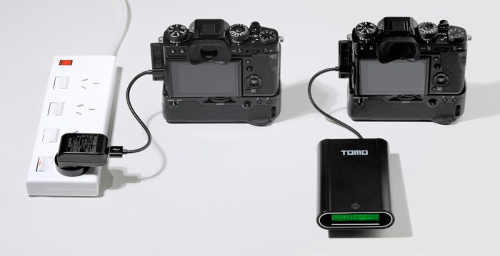
SECTION – I
POWER BANKS
A power bank is an external battery pack that can deliver power for charging or operation of mobile electronic devices, including digital cameras. The power bank’s input and output are usually (but not always) via USB ports.
ADVANTAGES
Power banks allow portability and versatility. One big advantage is that the power they hold can be assigned to devices in an ad hoc manner (for example, to charge the camera, a smartphone, a tablet, etc, as needed). A second advantage is the ability to recharge batteries on-location, if and as necessary. Although it could be argued that there is a time and weight advantage in carrying pre-charged NP-W126S batteries, rather than a power bank and USB charger, the price difference between several genuine batteries, and a power bank, may be the critical deciding factor.
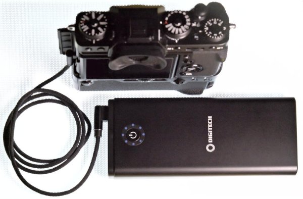
For high capacity power banks, the biggest advantage may be in powering the X-T3, in order to achieve extended running times. Note that, for the X-T3 camera, the power bank does not need to support the USB PD (Power Delivery) function, although having PD would be preferable. In general, a power bank without PD function, may be sufficient for stills photography, but for extended duration video usage, a high capacity PD power bank would be more suitable.

BRANDED POWER BANKS
It is recommended only to purchase branded (traceable registered brands) power banks, with good long term usage reviews. Unbranded power banks may state exaggerated capacities, have sub-standard internal assembly, and use un-matched cells (not matched for internal resistance) which will ultimately lead to reduced performance or even unit failure, depending on how the internal cells are connected (series, parallel, or combination).
PORT CAPABILITIES
Input ports (for charging the power bank) are typically Micro B type, or USB type-C. USB type-C ports, if PD capable, are bi-directional (marked “IN/OUT”). Not all type-C ports are PD capable. Sometimes, the type-C port is provided, simply to enable use of more recent power adapters, which may have a type-C cable. Output ports (for drawing power from the power bank) are typically USB-A, or type-C.
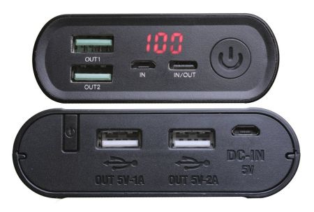
Since the USB Consortium maintains compatibility between different generations of USB standard, either type can be used, as long as the correct cable is available.
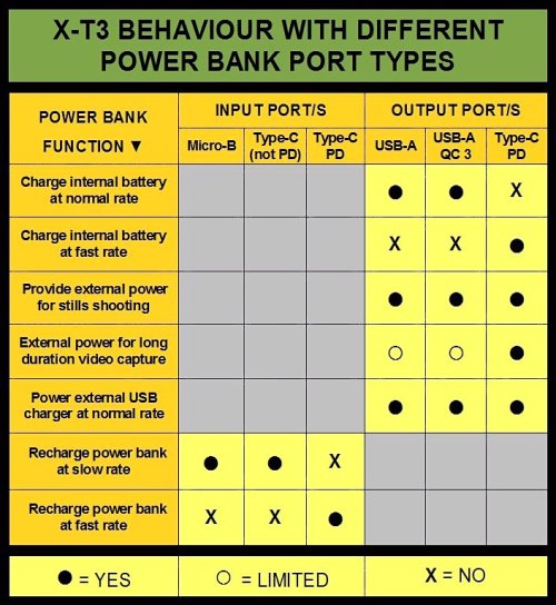
In the context of the X-T3 camera, USB-A ports which are designated as Quick Charge 2.0/3.0 ports, do not offer any advantage over standard USB-A ports, since the X-T3 does not recognise the QC protocols. However, the type-C ports which are designated USB PD, will allow the X-T3 to draw higher current (up to 1500mA, compared to up to 900mA drawn from a non-PD port). Power banks which offer lower capability ports (micro-B and USB-A) as well as higher capability ports (type-C PD) give an advantage of allowing the user to select charging and supply rates, by selection of the appropriate input or output ports (with the appropriate cable, of coures). Although fast charging is convenient (and sometimes necessary), lower rate charging is in the long term, beneficial to the longevity of the power bank.
EXPECTED OUTPUT CURRENT
Expect the X-T3 to draw up to 900mA of current from a power bank’s standard type-A output port, regardless of the port’s “marked” maximum output, which may be 1 Amp (1000mA), 2 Amps (2000mA), or even Quick Charge 3.0 (3000mA). If the power bank has a type-C “PD” (Power Delivery) output port, expect the X-T3 to draw up to 1500mA of current from that port. The nominal voltage will always be 5 Volts, regardless of the supply’s scalable voltage capability. Because the X-T3 will not (based on experience) draw more than 1500mA at 5 Volts (7.5 Watts), a power bank with an 18 Watt power capability would be more than enough to supply the X-T3’s power needs. There is definitely no need for a PD supply with higher power (Watts) output capability. Be careful not to confuse output current in milli-Amps (which affects power), with nominal capacity in milli-Amp-hours (which affects the running time that you get from the power bank).
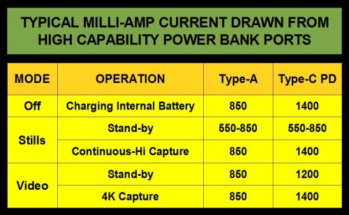
When comparing the current supplied by the Type-A port and the Type-C PD port, any supply deficit (the shortfall in the Type-A port’s supply) must be made up by the X-T3’s internal battery. However, if the usage is non-continuous, and the camera is allowed to auto-power-off, the internal battery can recover some of that power through internal charging while in the “Off” state.
REMOVABLE BATTERY POWER BANKS
Power banks that allow the batteries to be removed (sometimes referred to as DIY power banks, because the device is delivered without batteries, which the user must supply), offer many advantages:
• You can use the highest quality batteries, (You get to choose).
• Batteries can be replaced when their performance starts to decline.
• Batteries can be “borrowed” for other purposes (LED torch, for example).
• Spare set/s of fully charged batteries can be taken, on long expeditions.
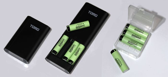
An important consideration for removable battery power banks, is whether the internal cells have their own individual channels for charging (as in the Tomo units), or if the cells are all on a single charge/discharge circuit. In power banks with individual channels, the cells do not have to be matched (for balancing), and can differ in brand, capacity, age, and even state of charge.
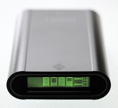
With such a power bank, it is possible to give the individual status of each cell. However, to maintain balance between the internal cells on power banks where cells are all on the same charging circuit, the cells must be matched (they should be the same brand and type, and even from the same batch – indicated by having exactly the same production code). Ideally, the cells should be matched to have the same internal resistance, but most users do not have the equipment needed to make this determination.
EXPECTED EFFICIENCY
Power banks normally contain an array of lithium-ion (or lithium-polymer) cells. The Panasonic NCR 18650B Lithium-Ion cells, are typical of the cell type used in many power banks. Due to economy-of-scale in their manufacture, eight of these would probably cost less than the price of one NP-W126S battery. (Although these 18650 cells would be typical of the cell type used in thicker bodied power banks, the ultra slim type power banks would usually use lithium-polymer “pouch cells”, which are relatively flat). The NCR 18650B energy capacity (3340mAh nominal capacity x 3.6 Volts nominal voltage), is approximately 12 Watt-hours, per cell. (The new Sanyo 18650 GA cells are 3500mAh nominal capacity, so 12.6Wh of energy). In contrast, the energy capacity of the NP-W126S battery (minimum capacity of 1200mAh x 7.2V) is 8.7 Watt-hours. By converting the specifications to energy capacity in Watt-hours, it is easy to compare cells and batteries of different voltages.

A large power bank could contain perhaps eight of these 18650 cylindrical cells (or the equivalent in pouch cells). However, real electrical systems are never 100% efficient, and there are always losses, especially when voltage conversions take place. When supplying power from a USB power bank, there is an initial conversion from the 3.6 Volts of the power bank’s internal cells, to the 5 Volt USB output, (and then a further conversion within the camera, from 5 Volts to the various internal voltages required by the X-T3). The 3.6 Volt to 5 Volt conversion causes a notable reduction in available energy, so, to achieve a more realistic estimate of the power advantage of the power bank supply, you can compensate the power bank’s energy capacity by a percentage that allows for the 3.6V to 5V conversion losses. Since we don’t know the actual loss values, you can assume 90% (or 85%) efficiency, and subtract 10% (or 15%) to allow for conversion losses. Then you can divide the remaining Watt-hours energy capacity by the 8.7 Watt-hours of the NP-W126S battery, to find the “number of batteries” equivalence of the USB power bank. So, in the case of a 20000mAh power bank (20Ah x 3.6V = 72 Wh), the finally available energy capacity (after a 10% reduction to allow for conversion losses), might be taken to be about 64.8Wh, which is about 7.4 times the NP-W126S’s energy capacity.
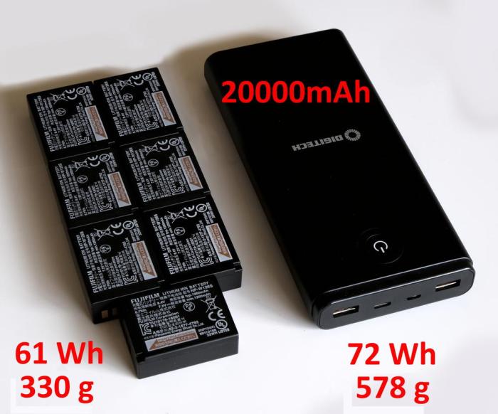
Sealed (not designed to be opened by the user) power banks, usually don’t specify what type of cells, or how many, are inside the power bank enclosure, but assuming that the stated milli-Amp-hour capacity is reliable, you can use a lithium-ion cell voltage of 3.6 Volts (or 3.7 Volts for lithium-polymer), in order to determine energy capacity in Watt-hours.
MULTI-VOLTAGE BANK VOLTAGES
Although most common power banks are designed to deliver power according to USB standards (normally 5V), it is also possible to get multi-voltage power banks. These may be of interest to the X-T3 user, since the grip can be connected to a 9 Volt power bank for charging and camera operation, and the body (without grip) can accept the DC coupler powered by a 9 Volt power bank, for operational power.


If supplying a nominal 9 Volts via the grip’s DC socket, the low range tolerance is about −3%, so the voltage should not go below about 8.75 Volts; otherwise the display will flash the low power symbol (red battery with no bars), and the camera will auto power-off. However, this low range cut-off does not apply when supplying power via the CP-W126 DC coupler.
BICYCLE LIGHT BATTERY BOXES
These battery boxes are designed to power high performance lighting on push-bikes. Some of them provide both a 5 Volt USB output as well as a nominal 7.2 Volt (8.4 Volt maximum) 5.5mm male DC plug output which is suitable for connection to the X-T3 via the DC coupler (with a suitable conversion cable). Note that this voltage is not high enough for the vertical grip’s DC input socket, however.

Two significant features of these battery boxes are, provision of strap lugs for secure mounting, and a high degree of weather sealing (since they are intended for mobile outdoor use).

These battery boxes usually take 18650 type cells. Ideally, each pair should be matched for internal resistance. The USB output is by a standard type-A connector.
POWER BANKS RECOMMENDED BY FUJIFILM
Fujifilm is currently recommending:
Anker PowerCore Speed 20000 PD, and
Anker PowerCore+ 26800 PD, power banks.
These have both USB-A and type-C ports. Whenever type-C PD ports are provided, they should be used in preference to the USB-A or type-C (non-PD) port, because the type-C PD port can potentially deliver more current. The PD port can deliver 5V at a maximum of 3000mA, (although the X-T3 only draws 1500mA), compared to 900mA from the USB-A port.
CAPACITY LIMITS FOR AIR TRANSPORT
For the purpose of implementing air transport safety regulations, lithium-ion (and lithium-polymer) batteries, are categorised according to their energy capacity in Watt-hours. In this context, a power bank is considered to be a “battery”. The lowest and least restricted category is 100Wh or less. A power bank with over 100Wh of energy capacity would not be allowed to be carried on a passenger aircraft without the specific approval of the airline.
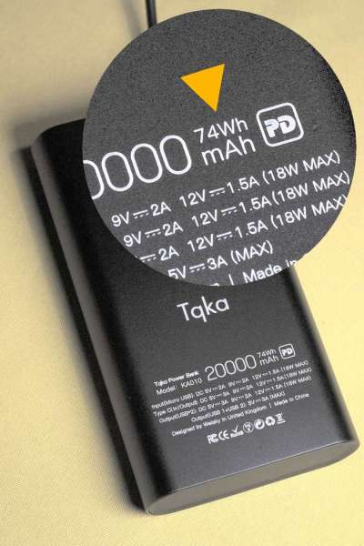
The energy capacity in Watt-hours can be found by multiplying the rated capacity by the nominal voltage of the internal cells. Assuming simple parallel connection, we can take 3.6V as the nominal voltage for lithium-ion cells, and 3.7V as the nominal voltage for lithium-polymer cells. If in doubt as to the type of cells, use 3.7 Volts. The 100Wh category limit explains why we see that very high capacity power banks seem to be limited to about 26800mAh (26.8Ah). The energy capacity of a 26800mAh power bank would be 26.8Ah x 3.7V = 99.2Wh, which is just inside the 100Wh limit of the least restricted category for air transport. Allowed units need to be taken as carry-on baggage, not checked-in baggage.
Section – J
DC COUPLER

The DC coupler is a common method used by camera manufacturers to provide a camera with an optional DC power socket. The DC coupler replaces the normal battery, and can provide a virtually continuous and unlimited supply of power.
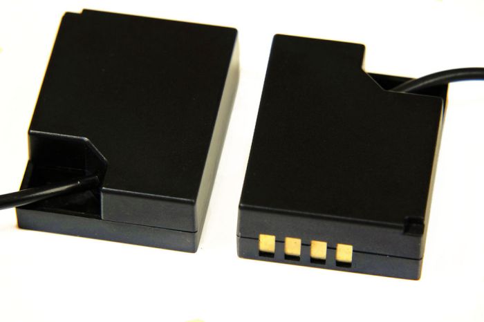
ATTACHMENT
The cable exit-point is on the right-hand side of the battery chamber door. When the door is open, and the battery removed, you can use a finger-nail to pull up the rubber seal. The seal is anchored, so that it doesn’t fully come away from the body.
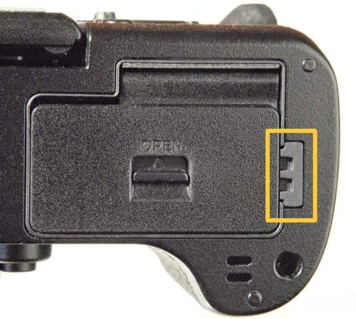

After inserting the DC coupler, with the cable on the exit-point side, ensure that the cable feeds properly through the exit route, and close the battery chamber door. The camera can now be powered via the DC socket which terminates the DC coupler’s cable. Remember to set the power Auto-Off setting to “off” to prevent the camera turning off automatically.


9 VOLT SUPPLY
The Fujifilm CP-W126 DC coupler combines with the AC-9VS power adapter to power the X-T3. A further possibility is to use the coupler to connect another appropriate (9 Volt) power source, for field usage. Because the maximum voltage of the NP-W126S battery is 8.4 Volts, an input voltage higher than 8.4 Volts, alerts the camera that power is being input via the CP-W126 DC coupler, and the “external power” symbol will be displayed instead of a battery level display. The rating for the power supply to the DC coupler is 9 Volts at 2 Amps (therefore, 18 Watt), and these specifications should guide the choice of power source. One possibility is a multi-voltage power bank which includes a 9 Volt output. The USB booster cable (described in section D), can also be used, to power the body via the CP-W126, from a 5 Volt USB power bank. However, this will only be able to deliver about 1 Amp of current, and so, would not be suitable for operation at the very highest performance levels, since there will be no internal battery to supplement the DC coupler’s supply.
D-TAP
The V-Mount battery system is a portable external power system widely used in professional video and cine production. (An alternative system is the Gold-Mount system, to which the following information also applies). The system allows very high capacity battery packs to be attached to a battery plate, which can itself be mounted to a video camera rig, a tripod, or a light stand, etc. As well as standard co-axial DC power output sockets (most commonly, 12 Volt), the system also allows access to power via D-Tap plugs, that fit into sockets which can be on the battery pack, or the mounting plate.
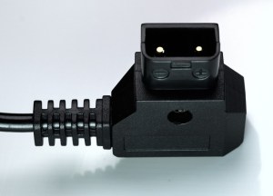
The standard voltage of the V-Mount and D-Tap system (14.4 Volts nominal, and 16.8 Volts maximum) is too high for the X-T3’s maximum of 9 Volts, however, a special voltage reduction cable can deliver the correct voltage to power the X-T3. Never connect a D-Tap output directly to the X-T3 without a suitable voltage converter.
A D-Tap to X-T3 connection will consist of three main parts: a cable with male D-Tap access plug, an in-line voltage converter to reduce from 24 Volts (maximum) down to 9 Volts, and a CP-W126 DC coupler.

These may be available as separate units, or one single cable with D-Tap, converter, and DC coupler.

The benefits of utilising the V-Mount and D-Tap system are, very high power storage capacity, the ability to power multiple devices (camera, external monitor, external HDMI recorder, video light, etc) from a single power source, built-in charge and charge monitor functions, as well as utilising the V-Mount plate and battery to counter-balance the front-heavy load of the camera in a video rig.
DC COUPLER APPLICATION
• Camera operation over long periods of time
• Static operations where the camera remains in a fixed position
• Situations where an interruption of operation must be avoided
• Situations where camera operation is be left unattended / un-monitored
• In situations where camera over-heating is an issue (for example, continuous 4K recording), removal of battery from the body can reduce number of contributors to internal camera heating
APPLICATION EXAMPLES
• Time-lapse photography extending over many hours or even days.
• Large volume copying (for example, books or documents) where the camera is mounted in a fixed copying rig.
• Surveillance photography, or wildlife photography, with automated triggering, such as a sound activated trigger, or laser trigger.
CLOCK RESET
When DC coupler is used, since there is no battery in the camera body, if DC power is turned off for an extended period of time, the camera clock will be reset. However, the camera should be able to keep its internal clock battery sufficiently charged if external power is connected at least every couple of days.
SAFETY ISSUES
Due to the camera being tethered by a power cable, various safety issues must be considered, as a matter of priority. Possible hazards include those generic to the use of AC voltages, trip hazards from cords/cables, and possible topple-and-strike hazards from cable pulling against tripods.
NOT APPLICABLE WITH GRIP
Please note that the DC coupler cannot be used in the X-T3 concurrently with the grip, because when the grip is attached, there is no exit point for the coupler’s cable. However, the DC socket of the grip makes use of a DC coupler redundant anyway.
Section – K
ALTERNATIVE POWER SUPPLIES
Alternative power supplies open the opportunity to use the X-T3 remotely from mains power for extended periods of time.
AUTOMOTIVE POWER
Access to a motor vehicle allows the use of a 12 Volt to USB converter, or even the USB power socket built in to the dash of late model cars. The output should be at least 1.0 Amp, but preferably more.
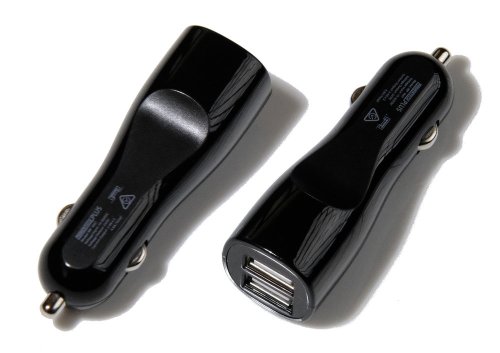
Although it is common for recent vehicles to have USB outputs as standard, many of them are limited to 1 Amp of current, so you may wish to use a plug-in converter, in order to access higher current.
BUCK CONVERTERS
A buck converter is a voltage step-down device. The example shown (Deek-Robot DK-D20252 Mini DC Power Supply) provides two regulated outputs: 5V, 2A (USB), and 1-20V, 2A, from a 8-20V, 2A input.

Such a device may be useful in situations where you want to use a range of different power inputs (12V AC converter, and 12V car “lighter” outlet), or where different voltage outputs are required for a range of devices requiring different power or charging voltages. in such situations, it can reduce the number of power and charging devices that need to be carried.
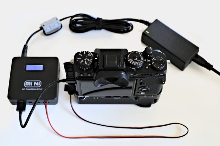
Several important warnings, when using this type of buck converter: The input voltage must always be higher than the output voltage (otherwise you can burn-out the converter). Make sure that the input current is sufficient to supply the output currents. And finally, be aware that if the buck converter fails, there is the possibility of the full input voltage being delivered at the output; so make sure that the need to use the converter is weighed up against this risk.
HOW TO USE SOLAR POWER
Small portable solar panels allow the opportunistic recharging of power banks, which can then supply the camera, as well as other remote location gear. Don’t ever connect the solar panels directly to the camera. Instead, use the solar panel to charge a power bank, and then later, you can use the power bank to charge the camera batteries (internally or externally). Many portable solar power-supplies, although they deliver power via a USB socket, have an output that is unstable and subject to interruption. The voltage can exceed the allowable USB voltage by several Volts (especially if the Sunlight is very intense), if not connected to a high-enough load to bring about the appropriate voltage drop. A removable battery power bank with high capacity batteries, should place enough load on the supply, that the voltage drops to within the proper range for charging the power bank. At any rate, a catastrophic over-voltage event damaging the power bank, or its batteries, is a small cost compared to the possibility of damaging the camera. Use an inline USB power meter, so that you can be sure of what voltages are being delivered.

A folding unit, like the one shown, can give some degree of power control in ultra-bright conditions, by not being fully opened. Fully opened in decent Sun, it can easily produce 5 Watts of power. At midday in the middle of Summer, at mid latitudes, and properly aimed, it can produce several Watts more.

Since high temperatures are not good for Li-ion batteries, the power bank or charger will need to be kept in the shade while charging, if the ambient temperature is very warm. You can use a radiant barrier material (such as metalised mylar bubble sheet) to form a shade cone for this. The conical shape is used because it is easy to form, tends to be self-supporting and resists collapsing in on itself. The weight of the power bank or charger, placed within it, stops the cone from opening out.

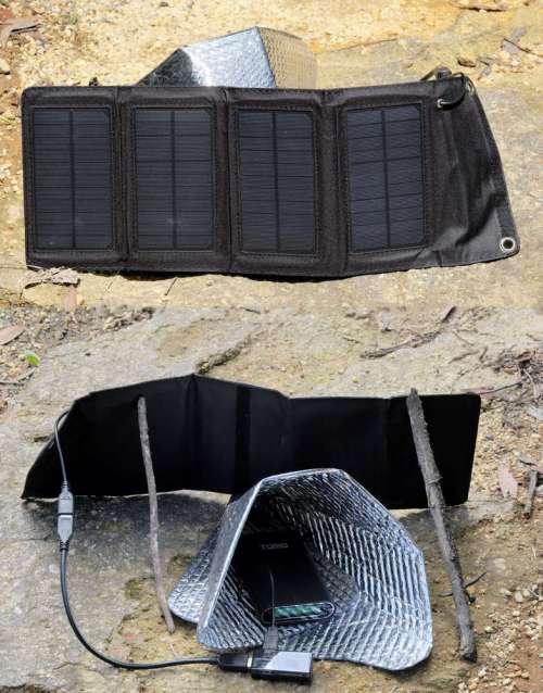
However, in very cold climates, the battery might benefit from being warmed up by exposure to the sunlight. A battery temperature in the 20’s of degrees Celsius, would be nice for the batteries.

If the Sunlight is not optimal, and if you have a removable battery power bank, rather than trying to charge the power bank, it may be more efficient to charge a single 18650 battery in a USB battery charger, and this battery can be swapped into the power bank when needed.
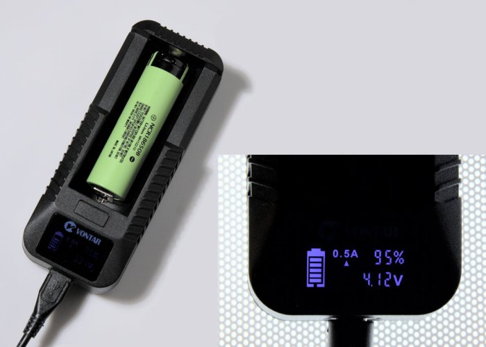
The solar charging system should not be set up near dried vegetation, due to fire risk. At times of extreme fire danger, it should not be left unattended at all. If you are on the move, and the Sun is at your back, you can do some charging opportunistically, by attaching the solar panels to your backpack.

Section – L
USB POWER METERS
One of the most useful devices for power management is the in-line USB power monitor. This device can display instantaneous voltage, current, and power throughput, as well as accumulated or drained milliAmp-hours, etc. Some also allow time, voltage, and current limits to be set. This device is very useful for charging situations where either the charger or the storage device (such as power bank) does not have a detailed status display. USB power meters are available with either USB type-A or USB type-C connectors.
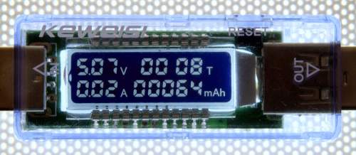

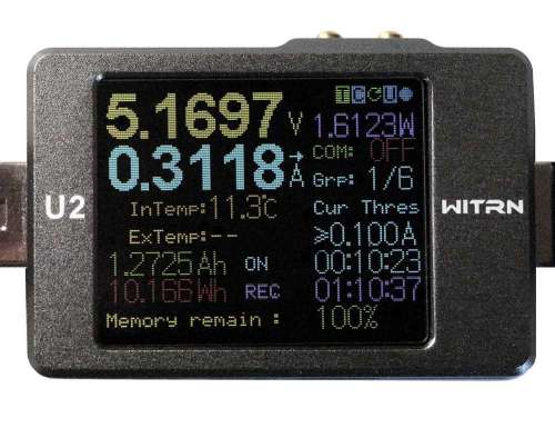
The displayed readings will reflect some discrepancies from losses due to the power monitor’s own processing and display and illumination, however the readings should be sufficiently accurate for our intended purposes.
VOLTAGE / CURRENT MONITORING
Although the camera’s LED indicator shows charging in progress or charging completed, the camera needs to be switched on in order to get a more detailed indication of current SoC, and charging progress.
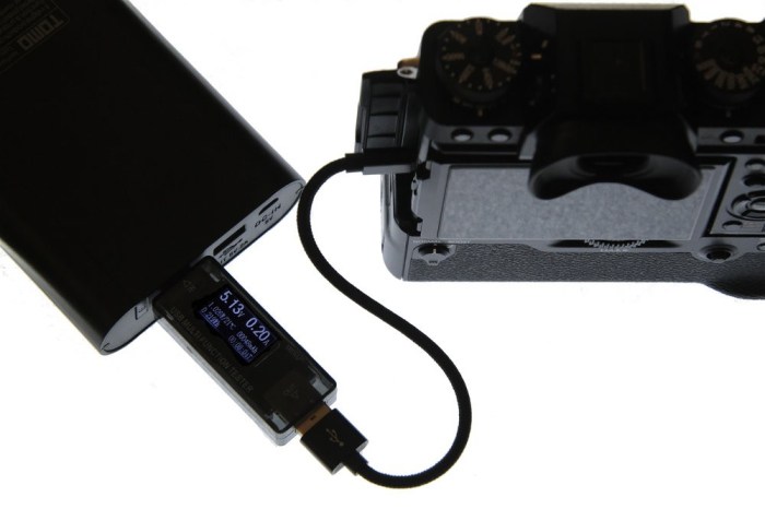
If a power monitor is inserted inline, it can continuously show the instantaneous supply current. The following chart gives approximate values, and does not account for conversion or other incidental losses.
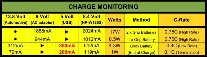
When using the USB port to charge the body battery, and using an inline USB tester, the present status of the supply current is a useful indicator of the position in the charging process.
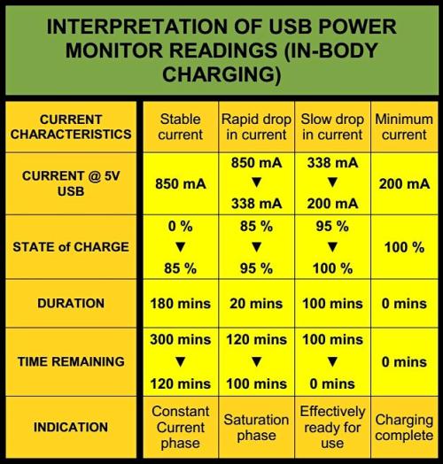
Because the actual charging current can vary according to battery condition (SoH), as well as environmental conditions such as temperature, the quoted values are mainly intended as a conceptual illustration of the significance of variations in current flow during the charge process.
Section – M
DISCLAIMER
Incorrect or inappropriate use of the X-T3’s power systems, could lead to damage or even destruction of the battery, camera, or other ancillary devices. Furthermore, catastrophic failure of the lithium-ion battery could lead to serious personal injury.
Before acting upon any information in this guide, the camera user should satisfy himself / herself that they are acting with due diligence.
This guide is a compilation of information that I collected for my own use of the X-T3 camera. I am making it available in the hope that some of the sometimes difficult to obtain information, may be of use to others. However I cannot guarantee the accuracy of all of the information given here. There is the possibility that some of this information may not be correct, despite my own good intentions and diligence. You, as the camera user, must verify this information for yourself, and decide whether acting upon it, is prudent and safe. I cannot be held responsible for any damage of injury.
Directives about powering the X-T3 are given in the Owners Manual. These directives include instructions not to use non-Fujifilm batteries and non-Fujifilm chargers. Usage that fails to follow these instructions, could have the consequence of voiding your warranty.
[ Last updated: 15 November 2019 ]
THANKS FOR READING . . .
Powering the Fuji X-T3
If you would like to support me in continuing to produce high quality reference material, like this, please consider donating, maybe even the cost of a coffee.
Thanks for your support!

All images © 2018-2019 Dom Varney
 Photographic images on this page are licensed under a
Creative Commons Attribution-NonCommercial-NoDerivatives 4.0 International License.

Fabulous article! Thanks for all your time for research and awesome analysis and use-case suggestions. It’s so rare to find such in-depth, properly-researched info online. I hope you get lots of donations to support you to do more of this. This article saved me time and money, and was a pleasure to read as well. Thank you!
Thanks Dean. I really appreciate your supportive comments. Ciao.
Thanks Dom for a fascinating article, it has given me a lot of information that is hard to find elsewhere. I love the XT-3, and this is a change from the usual reviews. Great work!
Thanks Ray. I’m glad you liked it. Enjoy your X-T3! Ciao.
Wow, that is thorough!
I was really interesting in seeing if Power Delivery is supported and how that would work. I suspect it isn’t and Fujifilm just suggested an Anker PD power bank because it’s one of the largest available but it would be pretty amazing to be able to fast charge batteries in a pinch. I don’t have a PD charger myself or I’d check on my X-T3.
Hi Ed. Yes, this is an area where the exact details need to be teased out. On one hand PD does offer enormous potential, but on the other hand (at least in terms of internal battery charging), the C-rate is always going to impose a limit, with 0.7C being the fastest they would normally like to use. I also don’t have (yet) a charging device offering the full PD specification, but mainly because my current external power device (the TOMO removable battery power bank) is meeting all of my requirements. Thanks for reading, and for your comments.
Speaking of USB, have you tried connecting the X-T3 to a USB C external hard drive? Or a smartphone? I’d love for Fuji to implement a way for me to transfer files off the SD card without a computer.
Hi Ed. I’m looking forward to exploring USB-C a lot more, but most of my equipment is pre-C. I did try a card transfer from the X-T3 to a USB-OTG (“on the go”) external drive with limited success. That works with some cameras, and not with others. I’ll try again with the X-T3, and see if I can sort it out.
Hey Dom! This article is insanely detailed. Learnt more about all my battery questions than I could have watching 20 odd videos. I’m about to get an XT-3. Was originally thinking of getting the Wasabi W126 batteries. Now I’m considering a power bank (my existing Mi 2i 20000 mAH with USB-A to USB-C 3.1 cable, or a new USB-C 18W capable power bank) as my backup power supply – plugged directly into camera. Do you think it would work?
Hi JayS.
That’s great to hear that you found the guide useful. Getting this type of feedback makes it all worthwhile, so thank you.
When you get the X-T3, you can use it with your existing power bank (with, as you said, a USB-A to USB-C cable). That can charge your in-body battery, when the camera is off, and even supplement the battery power when the camera is operating. I would be inclined to see if that meets your needs, and just upgrade the power bank if it can’t keep up with your usage.
I have not used the Wasabi batteries myself (although I am about to buy some for some comparison testing). However, I frequently hear that they tend to swell, relatively early in their lifetime. (The Fuji batteries, if charged in the Fuji charger or camera, do not swell). In the short term, and in the long run (5 years down the track), you will not get better performance from any of the third party batteries, compared to what you get from the genuine Fuji batteries. But, yes, the Fuji batteries ARE expensive. I usually recommend to professional photographers that they use only the Fuji batteries in their main working camera (which is what I do), and just incorporate the cost of a new battery every six months, into their pricing. But if your are not a professional, such a cost can be prohibitive. Actually, on some of my non-work cameras, I use Patona batteries. (Don’t tell anybody!) But even those are difficult to get outside of Europe , and the postage is expensive. If at all possible, I would aim at getting another spare genuine Fuji battery, which will turn out to be good value in the long term. But beware of very cheap “genuine” batteries sold on-line: they are usually counterfeits. (By the way, I have another guide on my site, regarding the identification of counterfeit NP-W126S batteries).
Regarding using a power bank to supplement battery power while the camera is operating, I am currently writing a very practical guide to show how to do that safely and ergonomically, although that guide won’t be ready for a few weeks yet. Actually, it will be incorporated into the existing “Powering the X-T3” guide.
Thanks for you positive feedback, and I hope that you enjoy using the X-T3 as much as I do.
Ciao!
Dom Varney
Hello! Thanks a lot for the amazing article. I was thinking of getting the atomos power station. I can figure out what type of cable I would need to use… Would it work? To power it directly through the battery grip’s 9v input? You can find the specs here https://www.atomos.com/power-station
Thanks!
Hi JK.
Thanks for reading my article.
Regarding the Atomos Power Station:
(Please keep in mind that I have not used this device, so I am just working from the specifications on the Atomos site). The Atomos PS looks like a very capable auxiliary power supply, especially for video oriented camera setups. However, there may be a few problems with trying to use it with the Fuji X-T3.
(1) The Atomos has two DC outputs at its front. They are both 8.4 Volts. However the X-T3’s grip DC socket requires 9 Volts. To test this, I removed all batteries from the camera, and tried powering it from a precision variable power supply, via the grip’s DC socket. At 9 Volts, the camera worked normally. However, at 8.4 Volts, the camera turned on, and after less than one second, showed the “red-battery” symbol (low power), and automatically switched off. So if your camera batteries became exhausted, and you were expecting the Atomos to supply the power, it won’t happen.
(2) With the grip removed, 8.4 Volts should be adequate via a DC-coupler (fake battery with power cable). After all, the normal battery is only 8.4 Volts when fully charged. However, you would not be able to attach the Atomos to the bottom of the camera, because it would interfere with the DC-coupler’s cable exit, due to the Atomos completely cover the battery chamber door. I checked this from size specifications.
(3) There should be no problems with connecting one of the Atomos USB outputs to the X-T3’s USB socket. However, X-T3 plus grip plus Atomos becomes very BIG, and significantly heavier. This might be OK if the camera is going to be installed in a video rig, but not so good for a handheld stills camera.
So, it may be useful for a video rig, but generally, I don’t think it would work well with the X-T3.
I hope this information helps you.
Ciao,
Dom Varney
This is really helpful information. Thank you!
Hi Nathan.
Glad you found it helpful. Thanks for reading.
Thanks very much for the extensive research and write-up. It’s very helpful to this new X-T3 owner. I do believe you mean “Patona” batteries, though, not “Patina”.
Hi Doug. I’m glad you found the guide helpful. Thanks for pointing out the typo, which I have now corrected.
Ciao.
This is it, everything you need to know about powering the Fujifilm XT-3 but were afraid to ask lol! Thank you so much for the useful information!
Hi Arsyl. Thanks for the very nice comment. All the best.
Hi Dom, do you know if there is any way to power the camera with v-lock batteries? And if so, could you list the items and specifications needed? I don’t know anything about electricity and don’t want to damage the camera by using wrong stuff! Thanks so much for your invaluable article!!!
Hi Jose. Thanks for reading my guide.
Regarding your question, the most important thing is to not connect the X-T3 to a higher voltage than it is rated for.
The X-T3 can accept 9 Volts input via the DC socket of the VG-XT3 grip, or via a CP-W126 DC coupler inserted into the battery chamber. You can’t directly input a voltage higher than 9 Volts. The V-lock batteries have a nominal voltage of 14.4 Volts, and a maximum voltage of 16.8 Volts, which is too high for the X-T3. However, you can access a V-lock battery’s D-Tap output by use of a voltage conversion cable, which will reduce the voltage to 9 Volts. As an example:
https://www.bhphotovideo.com/c/product/1449163-REG/indipro_tools_dtfxt3_d_tap_cable_to_fujifilm.html
This cable includes the D-Tap plug, voltage conversion module, and DC coupler (“dummy battery”). There may be similar cables available from other makers as well. Of course, when using the DC coupler, the camera does not hold an internal battery.
Also, some V-lock batteries have a 5 Volt USB output, and that could be connected directly to the X-T3’s type-C USB port (although with the restrictions that are detailed in my guide, such as the USB only “supplementing” the battery power). I think the conversion cable would be a better option.
Note that I have never actually used V-lock batteries with the conversion cable that I have indicated, so although I am confident that this would work, you should verify this information with your own research.
All the best!
Dom
Hi Dom, thanks a lot for taking your time to answer with such an useful information. I will definitely try it since it’s a way to counterweight my camera with my actual rig too. Thanks a lot for your help!!!
Thanks Jose. Actually, I would also like to follow this up myself (when I have the time). If it works, I will add it to my guide.
Hey Dom,
Incredibly thorough investigation. I am amazed how much work you put into this.
I have this USB PD battery bank https://www.amazon.com/gp/product/B072BD98CM/ref=ppx_yo_dt_b_search_asin_title?ie=UTF8&psc=1
Using the PD port it charges the camera, and the green light on the back of the body comes on, but only when the camera is turned off. When I turn the camera on the green light goes off, and I do not see any type of indicator on the screen it is charging.
Any ideas what is going on?
Hi Cory. What you are observing is the normal and correct behaviour. A USB power bank can supplement the internal battery while the camera is operating, or it can charge the battery while the camera is shut down, but not both at the same time. If you want to get maximum charge time on the battery, you can set the camera’s “auto power-off” to 15 seconds. Whenever the camera Auto powers down, it will go into charge mode straight away. And the wake up from Auto off is just a half second, half press on the shutter release. Thanks for reading the guide.
Wow, this is what you call a comprehensive review! Thank you for this amazing information.
You mentioned Fuji recommends the following power banks. Anker PowerCore Speed 20000 PD or Anker PowerCore+ 26800 PD. There’s a new smaller variation that’s just been released by Anker. It’s a bit smaller in size but the advantage is that you can strap it to your hotshoe without the bulk and used the PD function. For video shooting this would be great. From the specs on the Anker site how can I tell if this would work for the XT-3? https://www.anker.com/products/variant/powercore-10000-pd/A1235011.
Thanks again for the amazing write-up!
Hi Ariel.
That looks like a really great power bank. There should be no problem connecting the X-T3 to a power bank via its Type-C USB PD port; in fact, that is the recommended connection port, whenever available. However, be aware that the X-T3 does not “support” elevated power PD functionality. (I am very happy for anyone, with supporting evidence, to prove me wrong!) “Not supporting elevated power PD functionality” means, the X-T3 will not negotiate higher voltage or current than the port’s default (5 Volts at up to 3 Amps). The X-T3 will still only draw 5 Volts, at not more than 2000 milliAmps (typically about 1500 max), which is within the PD default specifications. That means, less than 10 Watts, not the power bank’s 28 Watt maximum. (The Fujifilm support page FAQ for “mobile batteries” does not make this clear). Other power banks, without PD, will work, but the maximum current supplied will be less. How much difference this makes will differ depending on whether you are doing stills or video. However, one big advantage of the power bank having PD, is that (using a PD capable charger), the power bank will recharge much quicker than a power bank that does not have PD. Non-PD power banks can be very slow to charge. Hope this helps with your evaluation of that power bank.
Thanks for reading my guide. Ciao.
So what you are saying is I can use any power bank it doesn’t need the PD function? What specs should I be looking for looking for with other power banks then? Most generic power banks output: DC 5V = 2.1A. Or is the idea that a PD gives you enough juice to be able to run off a battery where a regular power bank would not keep up with the power demand needed?
Hi Ariel.
On a power bank with PD function, even if the plugged-in device doesn’t support PD, the power will be available at the PD default values of 5 volts at up to 3 Amps (3000mA). On non-PD ports (the USB type-A ports), the maximum available power will typically be 5 Volts at up to 2 Amps (or 1 Amp). All of these will work with the X-T3, but the PD will work better.
If I attach an in-line USB power meter, I can measure the current being drawn by the X-T3. When I try all different types of power supplies, PD and non-PD, this is what I typically find (for charging or for 4K video):
– with a non-PD supply, the camera draws about 900mA at 5 Volts through the USB connection
– with a PD supply, the camera draws about 1400mA at 5 Volts through the USB connection
They both work, but the PD system is supplying more power. I have to assume that with the non-PD setup, the remainder of the power (the difference between 1400 and 900mA) is being supplied by the camera battery. On the other hand, every time I turn the camera off, it will go into charge mode, and replenish some of that battery power.
Whether or not you are able to continue all day will depend on many factors, such as the capacity of the power bank, how long your video takes are, how much recovery time between takes, etc. For some people, a good quality power bank that does not have PD, may still meet their needs. But for those with the highest power requirements, the PD power bank will give a significant power advantage.
Some people are saying that the power bank must have PD: that is not true, although a power bank with PD would be preferable. At the same time, we need to have realistic expectations about how much extra advantage PD will deliver. I hope this helps with your buying research. Ciao.
Hi Dom, on ebay and amazon there are lots of dc-coupler + usc “step up” cable + power bank, which is meant to power your camera, but i can’t find any satisfactory review about it. Do they actually work? In theory i can’t see why not, but I wonder if they won’t supply stable power or show one of those “red battery” signal, like you mentioned, after few seconds/minutes of usage.
Thanks in advance,
Felice.
Hi Felice.
Thanks for visiting my guide to “Powering the Fuji X-T3”.
In general, the USB 5 Volts stepped up to 8.4 Volts (equivalent to fully charged battery) by a boost cable, may work adequately for relatively low drain applications (stills photography, without heavy power demand functions such as continuous auto-focus, or high rate continuous shooting). However, in certain situations, it may not be able to continuously supply the power that the camera demands.
For example, a power bank may have a limit of 2 Amps for the 5 Volt USB-A port that you are plugged into. 2 Amps multiplied by 5 Volts gives 10 Watts of power. (The X-T3 is rated at 18 Watts; that doesn’t mean that it actually uses 18 Watts, but it is able to handle that amount of power, and the power can get quite high when internally charging its batteries). If that 10 Watts of power is supplied at 8.4 Volts, the maximum current available will be (10 / 8.4 =) 1.19 Amps (or, 1190 milliAmps). And that is without allowing for power losses due to voltage conversion. But I know (by actual measurement) that the X-T4, when recording 4K 59.94P at 200Mbps, draws at least 1.23 Amps, making the power consumption (8.4 x 1.23 =) 10.33 Watts. The X-T3, with similar settings, should give similar results. That is already higher than the 10 Watts the USB port can theoretically deliver, without even considering conversion losses due to the voltage boost. The system may run for a while, (some power banks allow 2.2 Amps from the A ports), but it would probably be running at close to its limit.
I think a better option is to use a power bank offering USB PD (Power Delivery), with an appropriate (PD) voltage conversion cable. Via the Type-C port, an 18 Watt power bank will be able to deliver 5V at 3A, (15 Watts), but also 9V at 2A (18 Watts), and possibly 12V at 1.5A (18 Watts). A higher rating power bank will offer even higher specifications, but those quoted are plenty for the X-T3 or X-T4. The type of cable needed, variously referred to as a “PD decoy”, “PD spoofing”, “PD deception” or “PD trigger” cable, will negotiate a 9 Volt supply from the power bank (and that 9 V might be further down-converted to 8.4 Volts), suitable for connection to the DC-coupler (“dummy battery”). The required PD protocol chip could be located in a box along the cable, in the USB Type-C plug of the cable, or even inside the DC-coupler, in an integrated setup. You need a 9 Volt (X-T3), or an 8.4 Volt (X-T3 or X-T4) cable. (I have not verified that 9 Volts can be used for the X-T4 camera). Most of these cable are not suitable, since they are intended for charging laptop computers, and do not have appropriate voltage outputs (most are 20 Volts!), or the correct DC connection plugs. However, if you are prepared to look, appropriate cables do exist.
Here is an examples of one of those cables:
https://www.aliexpress.com/item/4000245950792.html
The DC coaxial plug is likely to be 5.5 x 2.1mm, or 5.5 x 2.5mm, but many of the third-party DC-couplers available, have a 4.0 x 1.7mm female connector. In this case, a 5.5 x2.1 male to 4.0 x 1.7mm plug adapter is required.
https://www.aliexpress.com/item/1005001646882996.html
If you have the Fujifilm branded DC-coupler, the connection is via a 4.75 x 1.7mm connector, and again a plug adapter might be necessary. At the moment, there is no Fujifilm branded Dc-coupler for the X-T4 camera, but there are third-party versions.
Here is an example of an integrated unit for the X-T4. There is no longer a problem with matching the plugs:
https://www.aliexpress.com/item/1005001436117916.html
You should be able to find an equivalent unit for the X-T3 camera.
The examples I have given are simply to give you an idea of what is involved, and what is available. However, I cannot guarantee that they meet your needs, and I am not endorsing any particular equipment. Also, if you choose to go down this path, it is up to you to exercise due discretion, in determining that the setup is safe for your camera and equipment.
Ciao,
Dom Varney
This is amazing!
Thanks, Theo!
Hi Dom!! Great guide, I’m currently trying to find a way to use the NPF batteries to power up my XT3 though the Battery Grip,
I’ve found this adapter:
https://www.amazon.com/gp/product/B07NF14XW4/ref=ox_sc_act_title_7?smid=ATH7MH14Z4QBS&psc=1
And I’m thinking of using:
https://www.amazon.com/gp/product/B016BJGZ2U/ref=ox_sc_act_title_3?smid=A3TUR5JBYCEPNE&psc=1
https://www.amazon.com/gp/product/B00UJ9B2HW/ref=ox_sc_act_title_1?smid=A1THAZDOWP300U&psc=1
To connect to the battery grip.
Could you let me know if I’m on the right path, cause my other option was to use a power bank with the smallrig holder and don’t think that much, but I have lots of NPF batteries and was wondering if there was a way to use them with the XT3 (Also it would be a bit cheaper) !!
Again thanks for all the information on your guide, love from Peru !!
Regards!!
Hello Kinetic.
I just wanted to check a few things before I replied.
Unfortunately, you would not be able to feed the power from this battery plate directly into the battery grip. The cable and adapter that you identified will fit, but the camera won’t like the voltage (too low). The DC socket of the battery grip requires 9 Volts. Even the 8.4 Volts of a fully charged battery (including any of the NP-F batteries) is not enough. When you turn the camera on, it will, within one second, begin to show the red low battery symbol, and then the camera will auto power-off. I confirmed this with both a variable power supply, and with batteries.
On the other hand, the power from this battery plate could be fed into the battery chamber by use of a DC coupler (dummy battery). The cameras battery chamber will accept 9 Volts as well as the Fuji battery’s 8.4 Volts (fully charged) down to 6 Volts (discharged). (Of course, at 6 Volts, the camera will then auto power-off). This setup would consist of the battery mounting plate, the NP-F battery, and the DC coupler. I noticed that the company who makes the plate can also supply a DC coupler for Fuji cameras. I expect that its attached cable would already directly fit the DC socket on the mounting plate. You can get cheaper DC couplers (on eBay, for instance), however, their connecting cable has a female DC socket, of different diameter, so it would have to be changed, or a converter used. (The genuine Fuji brand DC coupler has a different cable socket size, the same as the battery grip socket, but that is the most expensive of the DC coupler options). By the way, you can’t use a DC coupler while the battery grip is attached, because the exit channel for the coupler’s cable would be blocked by the grip.
You could still use the battery plate, and connect one of its USB outputs to the camera’s USB type-C port. That would supplement the power of the internal battery. BUT, strangely, the camera won’t utilize that external power until any grip batteries have become depleted, then the external power will kick in. So if your grip batteries are fully charged, you can simply remove them from the grip, and the camera will use the external power straight away, (and you still have two fully charged batteries if you need them). Or, use the camera without the grip!
I hope this information helps.
-Dom
Hey Dom, a big thanks from all us new XT-3 owners and the many thankful who may not have the time to comment. This has benefited me immensely and being a wilderness shooter up here in northern Canada I figured out how to charge my devices.
I was given a gracious deal on an Anker Powercore+ 26800-PD / Anker 21W solar panel bundle. I have made sure to get the highest quality cables possible and went out of my way to grab a second genuine Fuji battery like you proposed above. When I’m moving, my solar panels hang from my backpack connected to the power-bank in a pocket which is then connected to my camera with a little slack/recover cord mechanism (so no tugs or tangles).
Adds a few pounds, but I have no power outlets in my areas for days sometimes.It is a little off grid solution that works great.
Hi Josh. Thanks for your feedback. I really love the solar panels, especially since my other equipment (flashlight, Handheld GPS, etc) is also powered from the power bank, so I think the extra weight is worth it. Great point you make about about the best cables. That is one of the places where you can lose some of that precious free energy. Ciao!
Wonderful information! Can I use the charger that came with the X-T3 to charge 126S and 126 batteries? I still have my X-T2 and don’t want to have to carry 2 chargers on the road.
Hi John. Yes, both batteries and both chargers are inter-compatible. On the accessories page of the Fujifilm global website, it states that the BC-W126S (the newer charger) supports “NP-W126 / NP-W126S”. The old charger will also have no problem with the newer batteries. Ciao!
Hi. i bought an oem cp-w126 dc coupler and since i couldnt find a ac-9vs i bought a center positive ac to dc adapter at 9v 2amps DC output. it works fine but after about 5-10 minutes of trying to get my capture card to recognize the hdmi signal while recording in 1080p 59 the camera was getting pretty toasty.. now im obviously a little concerned. am i doing something wrong? is the voltage too high? it reads 9.4volts dc on the multi-meter. is this too high? am i going to do damage to the camera?
Hi Brenden. I have the genuine AC-9VS, and I measured its no-load voltage with a multi-meter, and got 9.48 Volts, which is in line with your readings. Also, normally I would expect a tolerance of at least +/- 5% on the voltage, and again your voltage seems good. I don’t have any official maximum figures for the voltage, but I think your adapter sounds fine. Just to do a test, I ran my X-T3 for 15 minutes on 1080p 59 capture (however, using grip and 3 batteries), and with a small bead thermistor inserted between the LCD screen and the body. After 15 minutes, the temperature was reading 27.5 degrees Celcius / 81.5 degrees Fahrenheit (but the ambient temperature was cool, about 15 degrees C). The camera felt warm, but within my expectations, based on my experience. If the ambient temperature was higher, I would also expect the camera to get hotter. The camera should give you a temperature warning if it is going out of its temperature limits. Because I shoot mainly stills (and my video captures are typically short duration), it may be worthwhile getting onto some of the Fuji forums, and asking other video users about how much temperature rise to expect for various capture situations. It would be good if you are able to get some actual temperature measurements. However, hopefully, you are perhaps just being overly cautious. I hope this information helps you. Ciao!
Hi Dom-
Very nice and a great contribution to the knowledge base of the community- a truly good deed!
You may have given me a solution to this problem:
Going on safari next year, taking my XT2 and XT3. Mostly shoot stills with a little video. In the past I found that I went through at least 2 batteries/camera/day, so was planning to have six 126S. That’s a lot of money to spend. It also is complicated to charge that many batteries in the evenings.
Perhaps I could use an Anker Powerbank + 20000 (or similar) into the USB C power input to supplement the power in the camera used the most (with the long lens), and use regular batteries for the XT2 with secondary lens. That way I suspect I can keep the same 126S in the XT3 all day, and in the evening have to charge fewer batteries and of course the power bank too.
Thoughts?
Again, good work and thanks
Hi Jonathan.
A good power bank is certainly a more economic option than having a lot of (genuine) 126S batteries. However, the ergonomics (working with a cable attached to the camera), and logistics become issues. I would be inclined, if you can find a USB charger that you feel you can trust, to try having a battery on charge (or two in a dual charger), connected to power bank in your bag, during the day. The 20000 and 26800 mAh power banks can be quite heavy, and if you are not doing much video, a smaller power bank like 10000 mAh (actual, not “claimed”), might meet your needs. At any rate, the best advice would be to get together your proposed power setup, and do some trial runs, to see what is working for you, and what is not. If your safari is going to be in very hot conditions, you need to take into account how that will affect your power management, as well. Thanks for reading the guide.
Ciao!
Dom
Good advice, Dom. I think the USB charger connected to power bank is best bet. Any advice on a USB charger though? You did not seem that thrilled about them in the article.
Hi Jonathan. I’m still testing various chargers for my own remote-location use. For me, the main issue is always going to be whether the charger will keep the battery below the 45 deg C / 113 deg F temperature limit for charging. This can be addressed by (A), the charger implementing some type of temperature management, (B), the charger complying with the recommended C-rate for charging, and (C), careful attention and monitoring by the user.
You can find more information about this in another article of mine:
The Great Battery Brawl
Although it is an overly long read (you can’t finish it in under an hour), you can scroll through to section “[4] Temperature Management”, to find relevant information. Just to put things into perspective, the article is not intended to argue that “this option is better than that option”, but rather to identify the various issues the user may want to consider when making their own personal choices.
At the moment, my personal preference is for the JJC DCH-NPW126 dual slot USB charger. Despite its rather simple State of Charge display (flashing LEDs, where 1 flash = 25%, 2 flashes = 50%, 3 flashes = 75%, and steady = 100%), the charger has the following advantages: reasonably priced, dual slot, integrated USB cable, charging at the recommended rate of 600mA (regardless of whether 1 or 2 batteries are inserted), and a “claimed” temperature management strategy – “When the batteries are about to overheat, the charger will sense and stop charging immediately”. I would like to to verify this protection mechanism when I have the time. This would involve opening the charger, identifying the (I presume) thermistor circuit, and then while charging a battery, applying some measured heat to the thermistor, and checking that the charging terminates at a temperature not higher than 45 deg C. Since I havn’t had the time to do this yet, I am taking the temperature protection claim at face value.
Regarding the Nitecore FX1 dual slot USB charger, in my personal opinion, it may not live up to every user’s expectations. The integrated cable is very short and in-flexible, and with many power banks, the reading of accumulated milli-Amp-hours will regularly reset to zero, making that particular display useless. The temperature display (which is accurate for the genuine Fujifilm batteries), is a display only, and does not force the charging to terminate when exceeding the allowed maximum charging temperature. Furthermore, the display does not give an accurate temperature reading at all, for third party batteries. It is still, however, a very nice and high quality “smart” charger, even if rather expensive, and paired with the right power bank (one not prone to resetting), gives a wealth of useful information when charging the genuine Fujifilm batteries. The Nitecore is one of the fastest chargers available (fast because it will allow the batteries to charge at 1000 mA or higher), but that will make it even more important for the user to monitor the temperature, to ensure it remains in the safe range (safe referring to battery health, rather than fire or explosion danger, which typically occurs at much higher temperatures).
Charge rate is important because higher charge rates produce more heat. Charging at temperatures which exceed the allowed upper limit, will shorten the life of the battery, and may lead to battery swelling (with possibility of battery getting stuck in battery compartment), especially with some third party batteries.
Regardless of the charger used, I would also recommend developing the skill of estimating the approximate battery temperature by touch. If you get an old battery, and an appropriate thermometer (a non-contact IR thermometer might be best), on a warm sunny day, you can expose the battery to the sunshine, while measuring its temperature, and then feel and describe to yourself the sensation at various regular temperature points – say 25, 30, 35 and 40 deg Celsius (or say, 70, 80, 90 and 100 deg if you are working in Fahrenheit). The reason I say to use an old battery is because its thermal transfer, by touching the plastic case (polycarbonate in the case of the genuine Fujifilm batteries), will be different to that of an aluminium, stainless steel, glass, wood, or object of other materials. If you have this skill, then when you feel the battery while it is charging, you can make the call to interrupt the charging, and let the battery have some cooling time before continuing, whenever necessary.
Finally, charging at 600 mA will take several hours to fully charge an NP-W126S battery. If you did find that the camera battery had become depleted, while the spare battery was still not fully charged, there is no problem with swapping the partially charged battery into the camera. You will only get whatever charge it currently holds, but it is not bad for the battery (in fact the lithium-ion chemistry actually prefers not to be fully charged).
I hope this information is of some help to you. Ciao!
Hello! Your article is amazing! We would like some recommendations about the best pd powerbanks for xt3/xt30 in addition to the expensive official fujifilm recommended power banks. Actually I think they are already discounted.
Actually I just was to share you this interesting kickstarter https://www.kickstarter.com/projects/blindspotgear/power-cage-and-bracket-the-power-bank-for-film-makers
What do you think? Ideal for charging fuji xt3/xt30 or you see something wrong in the specs? Thanks in advance.
Hi FJ.
The Power Cage, which you linked to, looks very interesting. It has great mounting possibilities, although they do come at a power cost. For example, the Tqka KA010, at a similar weight and size, (and also with a better resolution “remaining power” read-out), gives twice the power.
Tqka KA010 _______ Power Cage
20000 mAh _______ 10000 mAh
74 Wh _____________ 37 Wh
398 grams _________ 320 grams
134x72x26 mm ____ 120x70x30 mm
Of course, mounting / securing the Tqka, as with most power banks, is problematic, so the power per weight/size trade-off of the Power Cage may be reasonable.
Also, a lot of people go for a PD power bank because they want to shoot video “for the whole day”. The quoted 3.3 hours for the X-T3, may not be sufficient power for videographers with this need. Because I mainly shoot video in studio, with AC power converter to the camera, I may not be the best person to comment on the benefits of this particular device. I hope some videographers with more experience in field usage might contribute their thoughts.
Thanks for reading.
Thank you a lot for the answer!
Thank you Dom for a fantastic article. I’ve an X-H1 for work and then my own X-T3 and this information is invaluable.
Glad to hear that it was useful, Michael. All the best!
Great article. I’m curious to know if it possible to power the camera with the battery grip attached using a
V mount battery. I’m building a rig and having the grip adds the weight I’m looking for. Any advice or suggestions for this?
Hi, Jamel-Rashad. Regarding the possibility of powering the X-T3 (or X-H1) with grip attached via a V mount battery: You can find some relevant information in the X-T3 article, in Section J (DC Coupler), if you scroll down to “D-TAP”. The standard output voltage of most V mount batteries with D-Tap (14.4 Volts nominal, and 16.8 Volts maximum) is too high for the grip’s 9 Volt DC input socket, unless a voltage down-converter cable is used. Also, if the set-up has a nominal 8.4 Volt output (as you would get from a two-cell li-ion battery, that voltage will be too low for input via the grip’s DC socket (however fine for input via a DC-coupler in the camera body). And you can’t attach a grip while using the DC-coupler, due to the cable exiting from the battery chamber. If the external battery set-up has a regulated 9 Volt output, the grip will be fine with that. However, the voltage can’t go below about 8.75 Volts; otherwise the display will flash the low power symbol (red battery with no bars), and the camera will auto power-off, if the camera is depending solely on the grip’s DC input for power. I hope these cautions will help you in finding your own optimal powering solution. Thanks for reading.
thank you thank you for sharing 😉
You are very welcome!
Really appreciate the detailed article!
I’ve got an XT30 which has the same power requirements as the XT3. The one issue I’m facing is that the USB C port blocks the HDMI and vice versa, they are extremely close. I want to power it for a handheld video rig.
Now I want to use a dummy battery with a power bank, I’m finding a few solutions. A power junkie kit that outputs 7.2V DC from a Sony L battery into the dummy battery of the XT30. Or, the USB power as you mentioned with the drive cable. Would the 7.2V be an issue? The power junkie can give up to 28W, and here’s a link with the item: https://www.bhphotovideo.com/c/product/1534820-REG/blind_spot_gear_blind_spot_gear_power.html
A few things I want to clarify: I can get a power bank that does USB-C PD at 18W (9V /2A) which matches the specs of external power, and also does 5V/3A over USB A which would be stepped up to around 7.2-8.8V with the drive cable. Would the USB A kit with the 5V 3A power bank work for 4K video at max quality (200 mbps)? That is more than the 1A you mentioned which would have issues.
I’m looking at the use of USB C PD into the DC Coupler, but the USB C PD protocol requires “negotiation’, so without a USB C PD to DC trigger, it won’t be able to properly power the camera and even then apparently the power bank can poll the camera and if it sees its not pulling power it will stop providing power.
I’m kind of at a loss here. I figured you would probably be the best person to ask for this since you really know your way around.
Hi Ali.
(My apologies for delayed reply).
You raised some very interesting situations.
Regarding the Blind Spot Gear Power Junkie, the 7.2 Volts output from the DC barrel socket, is just right for the X-T30. The NP-F550, NP-F750, and NP-F970, batteries, are all twin-cell batteries (as is the Fuji NP-W126S battery). For these twin-cell batteries, the Maximum voltage (and also the charging voltage) is 8.4 Volts. The minimum voltage is 6.0 Volts. As the battery discharges, the voltage will decrease from 8.4 down to 6.0 Volts. In order to get around this voltage variation, we quote a Nominal voltage, which is halfway between the maximum and minimum voltages. So, 7.2 Volts Nominal, and 8.4 Volts Maximum, which are the two voltages that you can find printed on your NP-W126S Fuji battery.)
Regarding USB PD, the PD functionality is not fully implemented by the X-T3 and X-T30 cameras: That is, they cannot request 9 Volts, even if the USB PD source is capable of supplying it. So the USB voltage will always be 5 Volts. As for the Current, in all of my USB tests, from many different USB PD power sources, and with the camera recording 4K video, I was never able to get the camera to draw more than about 1.4 Amps (1400 mA). That’s about 10 Watts (Nominal Voltage x Current). The 18 Watts specified by the camera is its maximum rating. In other words, it is able to safely handle 18 Watts of power, but whether it actually does, during normal operation, is another matter. I don’t think you actually need the 3 Amps. But a PD capable power bank will definitely be an advantage. The USB-A (non-PD) power banks will only deliver about 850 mA for 4K video, even though they are (generally rated for 2000 mA, which is often the total, between two ports).
Regarding USB C PD into the DC Coupler: As you said, without negotiation, the voltage will be the default, which is 5 Volts. 5 Volts is too low for an input voltage via the battery chamber, since the camera will take the 5 Volts to mean that the battery is flat (below the 6 Volt minimum), and either not turn on, or turn off within a few seconds. Even if you were able to negotiate for an elevated voltage (9 Volts), that voltage is too high for the camera, which expects a fully charged battery to be a maximum of 8.4 Volts. It is possible to reduce that voltage by about 1 Volt by use of an inline series diode, but now you have to get into some electronic engineering, and I prefer not to go there.
As for the USB PD power bank polling the camera, my investigations (using a U2 WITRN in-line USB PD power analyser) indicated that the X-T3 camera (and I assume the X-T30 behaves the same) does not respond to PD polling, so negotiation does not take place, and the supply defaults to 5 Volts at a maximum of 3 Amps (but the camera will only draw up to about half of that current). By the way, a high-end USB power analyser (like the type mentioned above), can perform the negotiation to achieve elevated voltage, but you really have to know what you are doing, and again, I prefer not to go there.
I think the Blind Spot Gear Power Junkie option that you mentioned sounds like a very good option.
I hope that this is of some help.
Ciao!
Thank you so much for your detailed reply! I’ve chosen the Blind Spot power junkie as my solution, and hopefully that gives me a good amount of juice to work with! Really appreciate your research and insight 🙂
Thank you so much for taking the time to research, and write this extensive post. It was so helpful.
Thanks for your feedback, Howard. You are very welcome.
Great article…. Another method I’ve discovered is to use on the the Sony L alternative battery/powerbank batteries with USB out to USB C into Camera. The battery can also be simultaneously used to power your monitor. While plugged in if you hit the “battery check” button on the battery it triggers the xt3 to see the power coming to it from the external power source and uses that too while still powering your external monitor.
Hi! after I conect Anker PD 20000 to x-t3 and its not powered battery while recording vide and operate camera – i read a lot in that article – but didnt find answers – why its not working )
Hi Serhii.
Thanks for reading my guide.
With regard to your query:
When a power bank is connected to the X-T3 via the USB port, the power bank does not replace the battery as the main power source. Instead, it “supplements” the power supplied by the camera’s battery, which still remains the camera’s main power source. In this power setup, the camera cannot operate without its internal NP-W126s battery. There must be one “at least partially charged” battery in the camera (or battery grip) for the camera to operate with USB power input.
So, if there is no battery in the camera, this setup won’t work. There should be a battery, but it does not need to be fully charged. Together, the battery and the power bank, will share the load of camera operation.
However, if there is a battery in the camera, but it does not have enough charge (that is, it’s virtually flat) then this setup will also not work.
Other things to keep in mind: When the camera is ON, whether for video or stills, the power bank does not charge the internal battery. However, when the camera is turned OFF, the power bank will begin to charge the battery. When the battery is fully charged, the power bank will automatically turn off. Unfortunately, with some power banks, when they “auto-off”, they sometimes remain off (no supplementary power) when the camera is switched on again. (I don’t have an Anker power bank, so I can’t say if its the case with that one). Sometimes you may have to push the power bank’s ON button, or even unplug and then plug in again the USB cable, to re-establish the connection. The USB standard generally allows “hot plugging” (removing and re-inserting the USB plug while the camera is operating), and I have had to do this sometimes.
Finally, problems can arise due to the cable being used; it is worth trying a different cable to see if it works. Or, it can be a problem with the menu settings for USB: Go to SETUP > CONNECTION SETTINGS > CONNECTION MODE > (and you will find) USB CARD READER / USB TETHER SHOOTING AUTO / FIXED / etc. Unless you definitely need to be in one of these modes, try different ones, and with different cables if necessary.
I hope one of these suggestions will solve your camera’s failure to operate with the power bank.
Ciao,
Dom Varney
Hi! Thank you very much for taking your time to write this article.
Unfortunately, I am not someone who knows anything about this stuff. Can you tell me if I’ll will be fine if I use an NP-F battery via NP-F battery plate (7.4V) to power my X-T3? On the back, and in your article, it says that the X-T3 accepts 9 volts…so I am little bit worried I might fry my camera in case I use dummy battery + this NP-F with 7.4V port. Thanks
Hi Aleksandar.
You should be OK to power the X-T3 by an NP-F battery using a dummy battery for input.
Just to clarify the Voltage situation: the NP-F series batteries are all a “nominal” 7.2 Volts (just like the NP-W126S battery). But when they are fully charged, they are about 8.4 Volts (just like the NP-W126S battery). After the battery is fully charged (8.4 Volts), the battery voltage drops rapidly when you start to use it, and when the voltage reaches 6.0 Volts, it is effectively flat. So the midpoint voltage (7.2 Volts) is considered a better “representative” or nominal voltage specification.
Because the X-T3 can handle 9 Volts via a dummy battery (the Fuji power adapter supplied with their genuine Fuji DC-coupler, or dummy battery, is a nominal 9 Volts), then even the 8.4 Volts of a fully charged NP-F series or NP-W126S, won’t result in “frying” the camera, since the input voltage is less than the camera’s 9 Volt “rated” maximum input voltage.
Some NP-F battery plates also feature alternative voltage outputs. But stick to the 7 Volt output. Do NOT plug into a 12V output! That would definitely “fry” your 9V rated X-T3.
I hope this explanation is of help. Ciao!